GSMV4G/GSMVCN4G Installation and Setup Guide
2-8
When calculating the total load on the auxiliary power output of the control panel, budget 10mA
for the communicator when using ECP mode.
Backup Battery Connection
The included battery (K14139) is used for backup in the event of power loss to the commu-
nicator. It does not provide power to the control panel.
In ULC installations this battery is not connected
, and all backup power is supplied by the
control panel.
• The battery can provide over 24 hours of system life in the event of a power failure.
• A programmable power loss message can alert the AlarmNet Control Center when system
power is lost (power loss messages are reported within 1-3 hours of actual loss).
• The communicator transmits a low-battery message (programmable) when the battery
reaches 5.7V ±5%, indicating subsequent messages may not be transmitted.
• The system shuts down when the battery reaches 5.1V, and radio transmissions are no
longer possible.
• If system power is restored before the communicator shuts down, a power restore message
is sent within 1-3 hours after power is restored, and the battery is recharged using the
communicator’s built-in battery charger. If system power is restored after the
communicator has shut down, a power-on reset condition exists, the communicator
initializes itself and the battery will recharge.
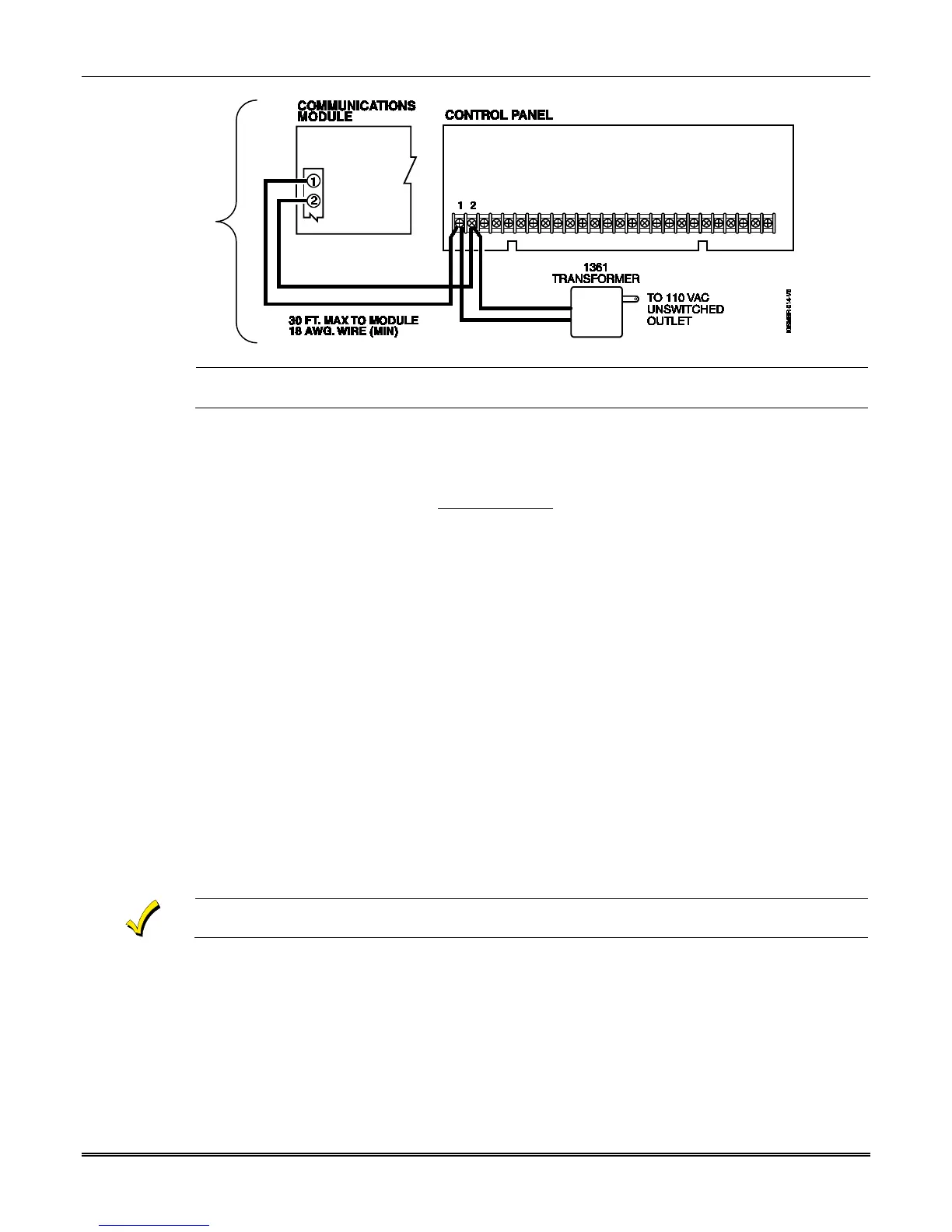
Install the battery as follows, and refer to the Summary of Connections diagram at the end of
this document.
1. Place the battery inside the case back.
2. Snap the right side of the battery clip onto the inside of the case back and secure the
left side with the screw provided.
Do not plug the battery in until after you have powered-up the communicator.
Initial Power-Up Sequence
Before connecting power, check that the following have been completed:
• If using ECP, 4204 or 2-4204 Mode, terminal block TB1 V+ and GND terminals are
connected to the control panel’s auxiliary power output: 12VDC nominal.
• Plug in the transformer. Then connect the red and black battery cables to the battery
terminals. Connect battery cable to connector J1.
• Power up the control panel. (Initially, all communicator programming options are set to
the factory default settings.)
Installation