ICON 100 SERIES USER GUIDE
EN2B-0002UK07 R0404
20
11. APPENDIX
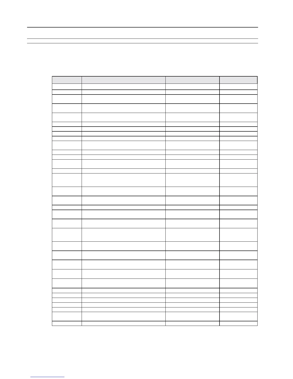
11.1. Appendix A – Default Factory Setting Parameters
The following parameters are for values that are based on a stand-alone controller
being used for a high temp application (dairy produce, fresh meat, chilled drinks
etc.), with electric defrost.
PARAMETER DESCRIPTION LIMIT / OPTIONS DEFAULT VALUE
d1 Main setpoint (d3 … d4) 0
o
C (+32
o
F)
d2 Differential (hysterises) 0…+ 20
o
C +1
o
C (+34
o
F)
d3 Lower limit of main setpoint -60…(d4)
o
C
-76…(d4)
o
F
-50
o
C (-58
o
F)
d4 Upper limit of main setpoint (d3)…+ 200
o
C
(d3) ... + 392
o
F
+90
o
C (+194
o
F)
d5 Minimum time interval between successive
switching of the compressor
0…999 s 120 s.
d6 Max. temperature alarm differential 0...+50
o
C +5
o
C (+41
o
F)
d7 Maximum or minimum temp. alarm delay 0…99 min. 20 min.
d8 Time interval between defrost cycles 1…999 h. 4 h.
d9 Max Defrost Cycle time 1…999 min. 30 min.
d10 Target defrost remperature -60…+ 100
o
C
-76…+212
o
F
+10
o
C (+50
o
F)
d11 Time period for supplimentary defrost 0…99 min 0 min.
d12 Defrost Recovery time 0…99 min. 30 min.
d13 Compressor function during defrosting 0 = always OFF
1 = always ON
0
d14 Drain Down 0…99 min. 2 min.
d15 Fan operation mode during normal controller
function
0 = linked to the compressor
operating mode
1 = always ON
1
d16 Fan activation delay at controller startup and
after defrosting
0…99 min. 5 min.
d17 Fan activation temperature at controller startup
and after defrosting
-60…+ 100
o
C
-76…+212
o
F
+5
o
C (+41
o
F)
d19 Display Offset -20…+20
o
C 0
o
C (+32
o
F)
d20 2k NTC and PT1000 probe selection 0= PT1000
1= 2k NTC
1
d22 Unit of temperature measurement 0 =
o
Celsius
1=
o
Fahrenheit
0
d23 Compressor function during a probe failure 0 = always OFF
1 = always ON
2 = timed ON & OFF
2
d24 Compressor ON time during probe failure 0…99 min.
(do not set to "0")
3 min.
d25 Compressor OFF time during probe failure 0…99 min.
(do not set to "0")
5 min.
d26 Local control or remote access control via
Genus
®
network
0 = Local, 1= Remote 0
d27
Stub number when connected to Genus
®
network
0…99 0
d28
Case number when connected to Genus
®
network
0…9…A…U 0
d29
Connect to Genus
®
Network
0 = Off, 1 = on 0
d30 Defrost cycle 1 time 00:00…23:50 hrs (00…235) 010
d31 Defrost cycle 2 time 00:00…23:50 hrs (00…235) 070
d32 Defrost cycle 3 time 00:00…23:50 hrs (00…235) 130
d33 Defrost cycle 4 time 00:00…23:50 hrs (00…235) 190
d34 First defrost cycle after controller startup 0= after 10 minutes
1= after d8 (hours)
1
d38 Minimum temperature alarm differential 0… +50
o
C (32...+122
o
F) +2
o
C (+35
o
F)
Table 5. Default Parameter Configuration
 Loading...