LYNX Touch Installation and Setup Guide
- 14 -
Installing/Configuring Communication & Home Automation Modules
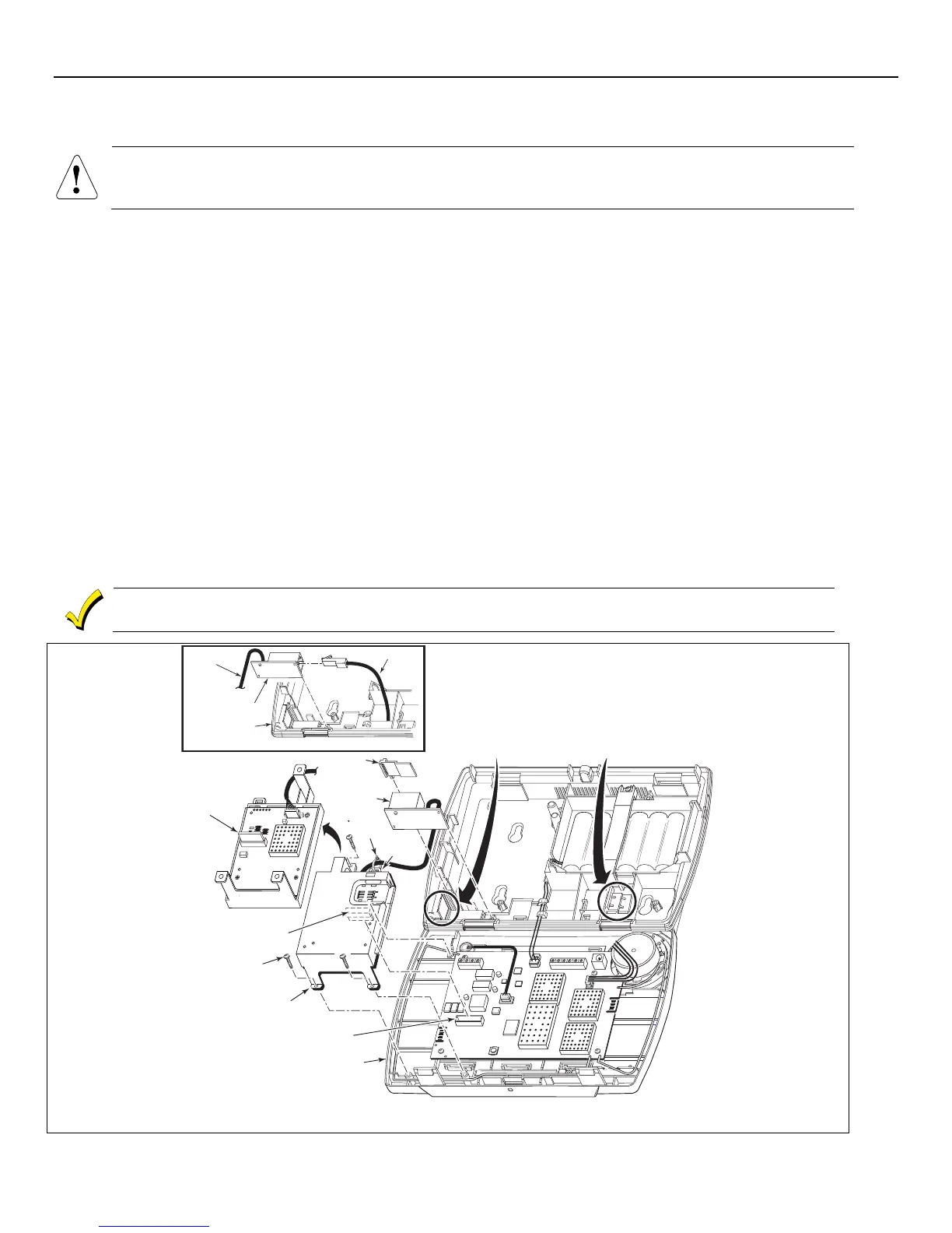
Installing the ILP5 Ethernet Communications Module
Do not install the ILP5 if the L5100-WiFi communications module is being installed.
Ensure that the connector board and cable are securely installed in the ILP5 before installing the
communications module in the LYNX Touch.
1. Using a wire cutter or knife cut the plastic tabs that secure the ILP5 spacer to the back case of the LYNX Touch.
2. Remove the ILP5 receptacle knockout from the left side of the LYNX Touch back case.
3. Install the ILP5 into the LYNX Touch control front case. Ensure that the connector board is properly seated into the
receptacle on the control.
4. Secure the ILP5 with the three provided screws.
5. Insert the ILP5 receptacle and spacer into the slot on the back case.
6. Secure the communications cable to the tie wrap point on the ILP5 with the provided tie wrap.
7. Connect the Ethernet cable to the RJ45 receptacle.
8. Enable the ILP5 and configure alarm reporting and module supervision and register the device. Refer to the “Program the
Communications Module” and “Communications Diagnostics” sections.
Alternate Installation (Refer to the Alternate Installation as shown on the figure below)
1. Install the ILP5 into the LYNX Touch control front case. Ensure that the connector board is properly seated into the
receptacle on the control.
2. Secure the ILP5 with the three provided screws.
3. Insert the ILP5 receptacle into the slot on the back case as shown on the figure below.
4. Secure the communications cable to the tie wrap point on the ILP5 with the provided tie wrap.
5. Connect the Ethernet cable to the RJ45 receptacle.
6. Enable the ILP5 and configure alarm reporting and module supervision and register the device. Refer to the “Program the
Communications Module” and “Communications “Diagnostics” sections.
he communications module must be registered with AlarmNet before downloading or alarm reporting can
ake place.
SCREW
(3)
5100-100-065-V1
ROTATED
180
CONNECTOR
BOARD
CONNECTOR BOARD
RECEPTACLE
ILP5
LYNX TOUCH
L5200
TIE
WRAP
POINT
REMOVE ILP5
SPACER
ILP5 SPACER
REMOVE ILP5
KNOCKOUT
TIE
WRAP
(1)
TO ILP5
LYNX TOUCH
ALTERNATE INSTALLATION
RJ45
RECEPTACLE
RJ45 RECEPTACLE
ETHERNET CABLE
L5200 IP Communications Module Installation
 Loading...