18 TK_S014 – Installation Manual
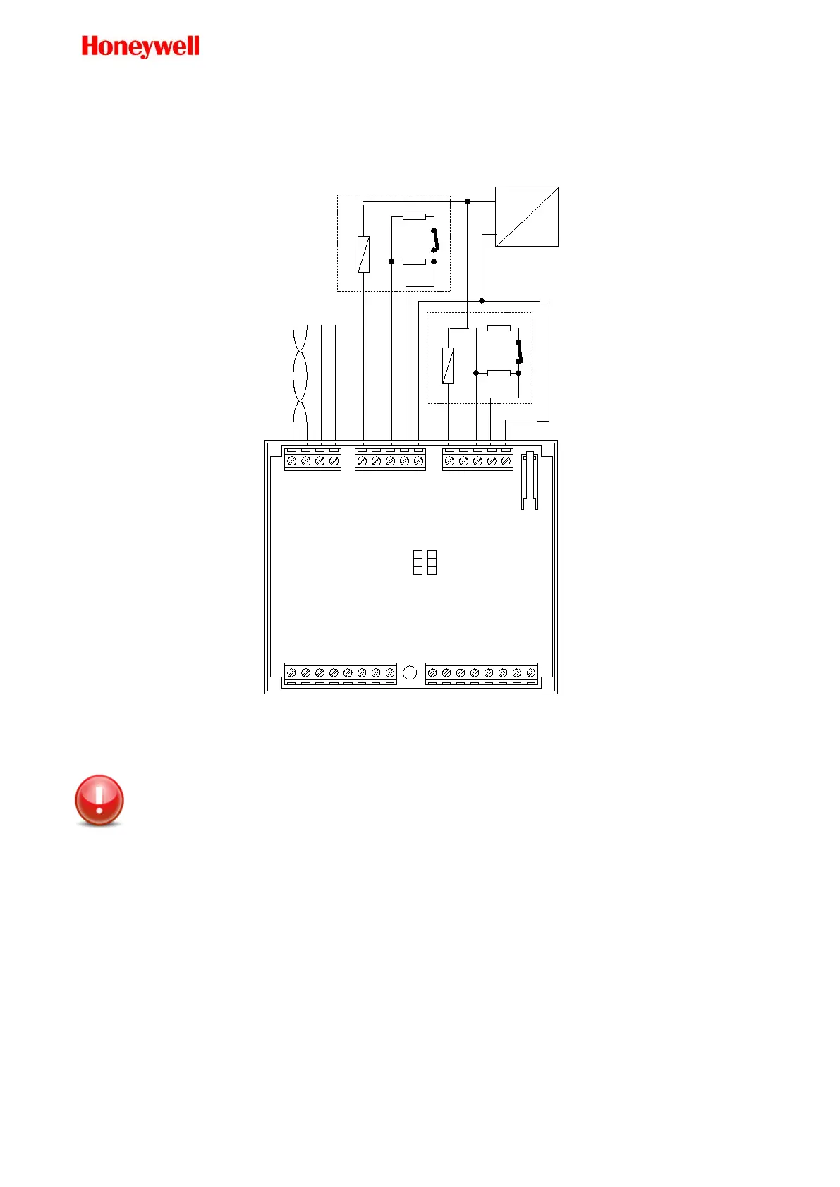
Door Connection (Using +V External Power Supply)
You may power the electro lock doors using an external isolated power supply (Voltage between 10 and
28VDC).
LONWORKS
POWER
ELECTROLOCK
White
Yellow
ELECTROLOCK
White
Yellow
switch
switch
OUT1
+12LOCK
OUT2
IN1
IN2
GND
GND
LON-A
LON-B
GND SUPPLY IN
+12V SUPPLY IN
GND
GND
WIE0-IN1
WIE1-IN1
LED-RED1
LED-GREEN1
BUZZER1
+12VRDR
+12LOCK
GND
WIE0-IN2
WIE1-IN2
LED-RED2
LED-GREEN2
BUZZER2
+12VRDR
GND
GND
GND
AC IN
DC OUT
Isolated
Power supply
GND
10 - 28VDC
JP1 JP2
1
2
3
Figure 12. Door Connection Using +V External Power Supply
Be aware that, even if the diode is already embedded in the unit, in some cases (long cable
installed near the inputs cables) may be useful to add an external diode provided with the
unit close to the relay device
Setting the normality value for the outputs
Jumpers JP1 and JP2 are used to set the normality value for the Output of the device. The factory setting for
the jumpers is Normally Open (NO).
• JP1 sets the normality value for the OUT 1
• JP2 sets the normality value for the OUT 2
When the jumper is set between position 2 and 3 the normality value for the related output is Normally Open
(NO). This is the factory position for the jumper.
When the jumper is set between position 1 and 2 the normality value for the related output is Normally
Closed (NC).
Rules for installation in harsh environment
 Loading...