T775 SERIES 2000 ELECTRONIC STAND-ALONE CONTROLLERS
63-7147—05 10
Chiller, Rotary Compressor – T775B
Application Description
The T775B is controlling the discharge water temperature of a
rotary compressor. The T775B provides an optional low
temperature or low pressure cut-out circuit.
NOTE: T775R reset models can also be used in this
application.
Sensor Designation
This device application only requires one sensor. Sensor A is
sensing discharge water and controls 1 or 2 compressors.
Operation
In this example, the cooling capacity of a Rotary Compressor
is controlled by a slide valve, which when moved towards
open or closed allows more or less refrigerant into the
compressor. Open and Closed solenoid valves position this
slide valve. The T775B is configured such that two relays are
used to position a single slide valve in a floating mode by
controlling the respective solenoid valves. Capacity of rotary
compressors may also be controlled by variable speed drives,
not covered here.
Programming Example
Relay 1: Compressor #1 controlling the Close solenoid valve
Program for:
—Cool
— Setpoint = 52° F (11° C)
— Differential = 2° F (-17° C)
Relay 2: Compressor #1 controlling the Open solenoid valve
Program for:
—Cool
— Setpoint = 56° F (13° C)
— Differential = 2° F (-17° C)
Relay 3: Compressor #2 controlling the Close solenoid valve
Program for:
—Cool
— Setpoint = 56° F (13° C)
— Differential = 2° F (-17° C)
Relay 4: Compressor #2 controlling the Open solenoid valve
Program for:
—Cool
— Setpoint = 60° F (16° C)
— Differential = 2° F (-17° C)
IMPORTANT
After the desired value is selected, be sure to press
the or or HOME button in order to save that
value in the controller’s memory.
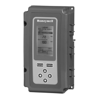
Wiring
All output relays should have a common power wiring source,
which may or may not be the same as the T775 power wiring.
See Fig. 5.
Fig. 5. T775B wiring — chiller, rotary compressor.
M24865
SENSOR A
(DISCHARGE WATER)
C
NO
NC
C
NO
NC
C
NC
NO
C
NC
NO
T
T
RELAY
1
C
+
RELAY
4
RELAY
3
RELAY
2
T775B
COMPRESSOR
#2
CLOSE
SOLENOID
COMPRESSOR
#1
OPEN
SOLENOID
COMPRESSOR
#1
CLOSE
SOLENOID
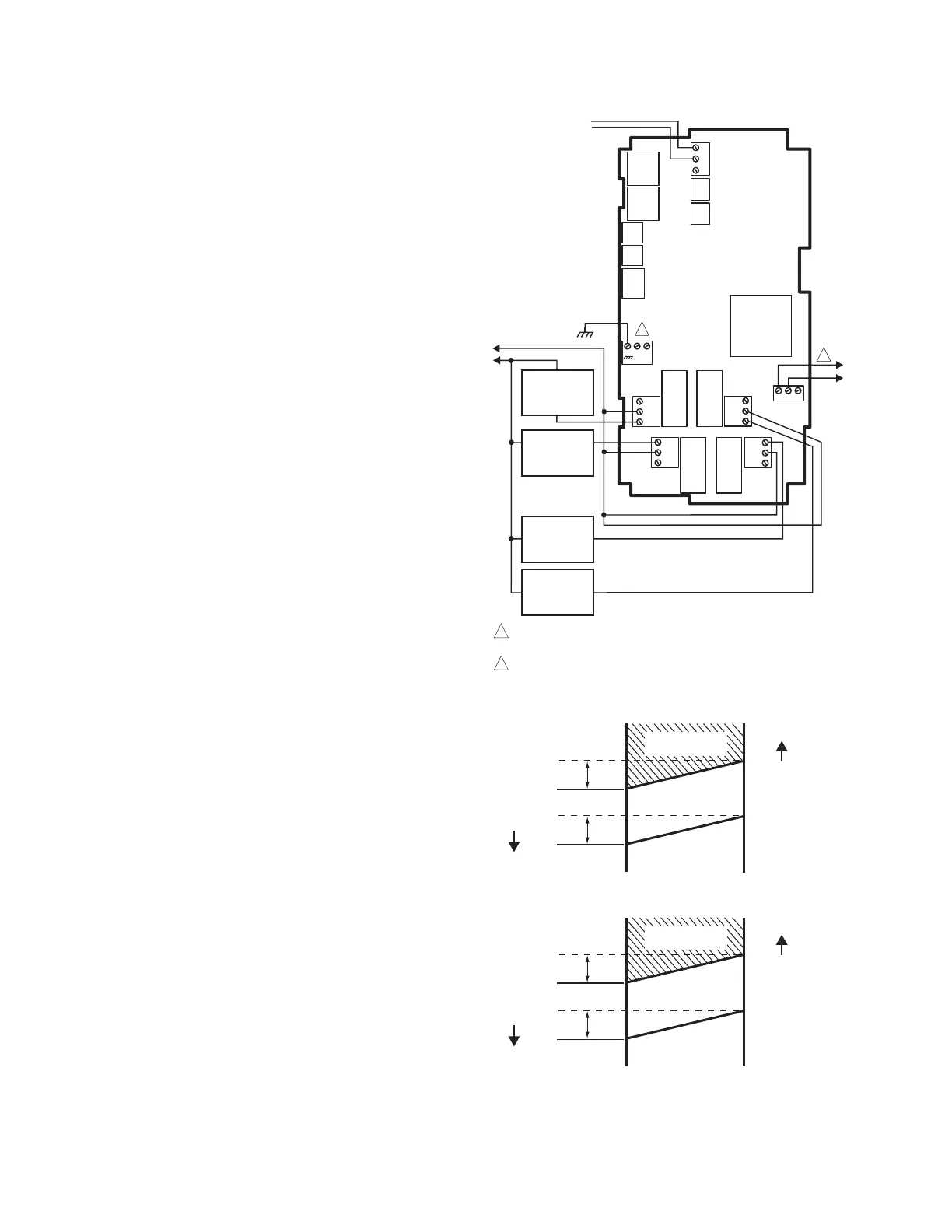
OPEN SOLENOID
ENERGIZED
NULL
CLOSE SOLENOID
ENERGIZED
56°
52°
2°
2°
COOL MODE COMPRESSOR #1
OPEN SOLENOID
ENERGIZED
NULL
CLOSE SOLENOID
ENERGIZED
60°
56°
2°
2°
COOL MODE COMPRESSOR #2
F
A
L
L
T
E
M
P
E
R
A
T
U
R
E
R
I
S
E
T
E
M
P
E
R
A
T
U
R
E
R
I
S
E
T
E
M
P
E
R
A
T
U
R
E
F
A
L
L
T
E
M
P
E
R
A
T
U
R
E
L1
(HOT)
L2
COMPRESSOR
#2
OPEN
SOLENOID
120
COM
240
1
2
120 VAC
POWER WITH 24 VAC OR 120/240 VAC AT THE APPROPRIATE
TERMINAL BLOCK.
24 VAC POWER TERMINAL BLOCK.
1
2
 Loading...