T775 SERIES 2000 ELECTRONIC STAND-ALONE CONTROLLERS
63-7147—05 26
Pressure with a Variable Frequency
Drive (VFD) – T775U
Application Description
In this application the T775U is controlling duct pressure with
a fan controlled by an NXS or NXL Variable Frequency Drive.
A P7640 pressure sensor, located in the duct, is providing
sensor input to the T775U to control the fan speed. The VFD
is looking for a 4-20 mA PID control signal from the T775U
and will drive the fan with a signal directly proportional to this
T775U output.
For additional information about the NXS or NXL variable
frequency drives (VFD), refer to the VFD Reference Guide,
form 63-9469.
Sensor Designation
This device application requires one sensor.
• Sensor A is sensing pressure at the duct (reference is at
the room).
Operation
In this example, as the sensed pressure decreases, the fan
speed increases. Assume we have a 0-10 Vdc sensor output
for 0-5 inches water column. First, set up a Sensor type of
0-10 Vdc into the T775U Sensor A settings, and a minimum
(0) and maximum (5) inches water column for the sensor
range.
Also set up a 4-20 mA PID modulating output loop (MOD 1) at
the T775U with a setpoint of 2.5 inches and a throttling range
of 2 inches, and a reverse acting action. At a sensed pressure
of 2.5 inches (in other word, at setpoint), MOD 1 will output
close to 50% or about 12 mA. At 1.5 inches water column, the
output will be 100% or about 20 mA, and at 3.5 inches water
column, the output will be 0% or about 4 mA. Keep in mind
these values are valid for proportional control and will differ in
a PID loop where integral (usually desired) and derivative
(less often required) are set to non-zero values.
Integral and derivative time may need to be adjusted, along
with the throttling range.
Programming Example
Program in Setup:
Press and hold the MENU button for 5 seconds to enter
Setup mode, and then select:
— Sensors
→ Sensor A:
Type = 0-10V
Units = IN WC
Minimum Value = 0.0
Maximum Value = 5.0
— Outputs
→ MOD 1 (Modulating Output):
Type = 4-20 mA
Program MOD 1 for:
— Setpoint = 2.5
— Throttling Range = 2 inches w.c.
— Action = REV ACT
IMPORTANT
After the desired value is selected, be sure to press
the or or HOME button in order to save that
value in the controller’s memory.
IMPORTANT
After programming the VFD, be sure to check the
following:
1. Verify that the VFD value P7.1.1.2 (AI2 mode) is set
to 2 (4-20 mA).
2. Verify that the jumper block X2 on the Expansion
board A is in Current Input Mode (a jumper is across
the A terminals, and a jumper is across the B
terminals).
3. Verify that the P7640A pressure sensor is set to:
Output = Voltage
Range = 0 to 5 inches w.c.
Mode = Unidirectional (default)
Volt = 10 Vdc
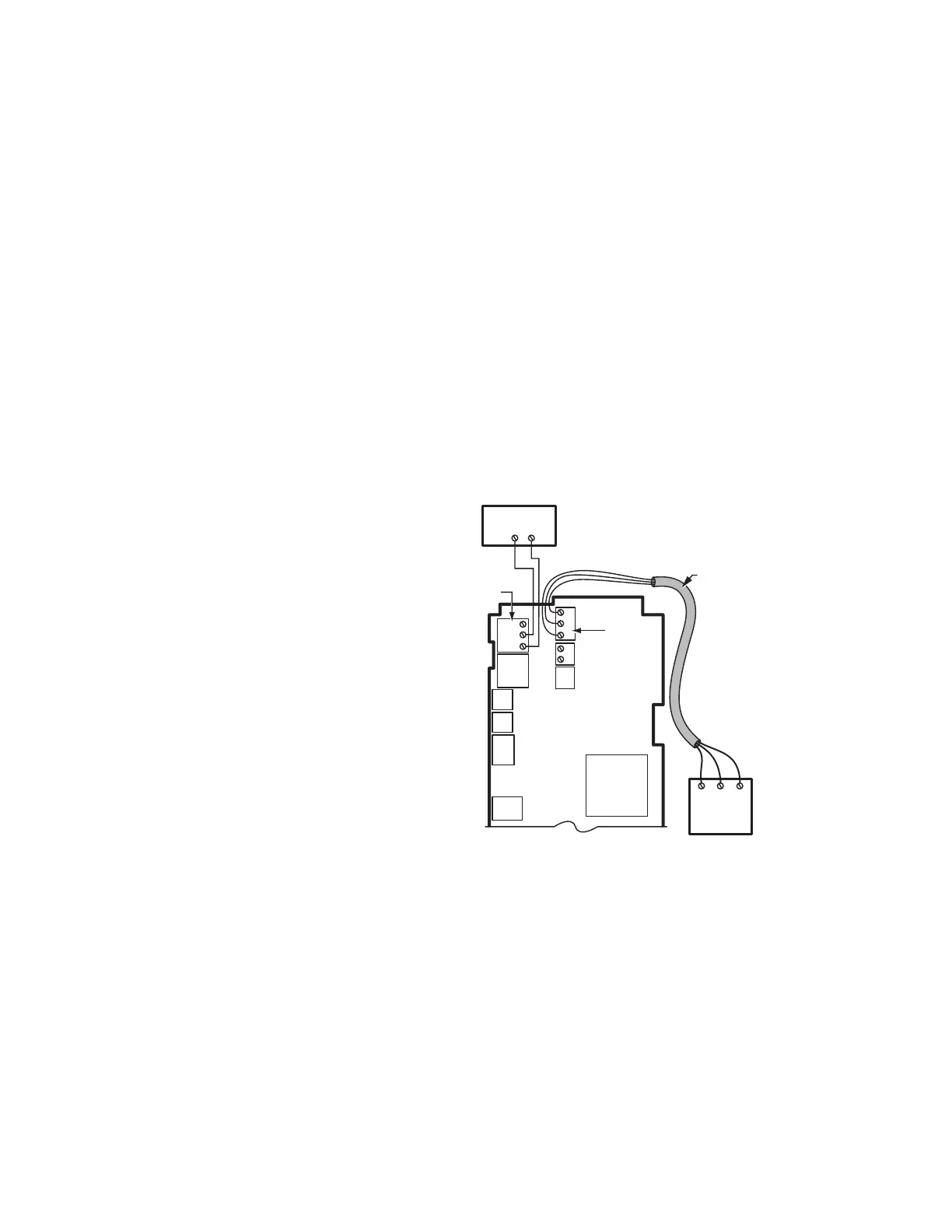
Wiring
See Fig. 32 for wiring connections for the T775U, the pressure
sensor, and the Variable Frequency Drive.
Fig. 32. T775U wiring — pressure with a VFD (loop
powered wiring).
M28006
SENSOR A
T
T
C
S
V
B
R
W
+
–
VFD BOARD A
54
MOD 1
POWER
OUT
COM
CSV
P7640A
PRESSURE
SENSOR;
0-10 VDC
CONNECTION
NOTES:
1. SHIELDED CABLE MUST BE
CONNECTED TO A SEPARATE
EARTH GROUND. HOWEVER,
DO NOT GROUND SHIELDED
CABLE AT SENSOR END.
2. TO MINIMIZE NOISE PICKUP,
MAKE SENSOR CONNECTION
FROM SHIELDED CABLE AS
CLOSE AS POSSIBLE TO
SENSOR BODY.
SHIELDED CABLE
 Loading...