T775 SERIES 2000 ELECTRONIC STAND-ALONE CONTROLLERS
9 63-7147—05
Chiller – T775B
Application Description
As the water temperature in the sump rises, the T775B
sequentially cycles on the spray pump valve and two relays of
fans. If the water temperature in the sump drops below 40° F
(4° C), the T775B energizes a sump dump drain valve to
prevent system freeze up.
NOTE: T775R reset models can also be used in this
application.
Sensor Designation
This device application only requires one sensor. Sensor A is
sensing sump water temperature.
Operation
In this example, the sump water temperature rises above the
Cooling Relay 1 setpoint plus differential 65° F (18° C) to bring
on the spray pump valve. If the temperature continues to rise,
Cooling relays 2; 70° F (21° C) and 3; 75° F (24° C) energize
the evaporation fans as needed.
If the sump water temperature drops below 40° F (4° C)
(setpoint minus differential), the sump water freeze up
protection is provided by energizing Heating Relay 4.
Programming Example
Relay 1: Controlling spray water pump and/or valve
Program for:
—Cool
— Setpoint = 60° F (16° C)
— Differential = 5° F (12° C)
Relay 2: Controlling fan # 1
Program for:
—Cool
— Setpoint = 65° F (18° C)
— Differential = 5° F (12° C)
Relay 3: Controlling fan # 2
Program for:
—Cool
— Setpoint = 70° F (21° C)
— Differential = 5° F (12° C)
Relay 4: Controlling dumping of sump at freeze condition
Program for:
—Heat
— Setpoint = 50° F (10° C)
— Differential = 10° F (-12° C)
IMPORTANT
After the desired value is selected, be sure to press
the or or HOME button in order to save that
value in the controller’s memory.
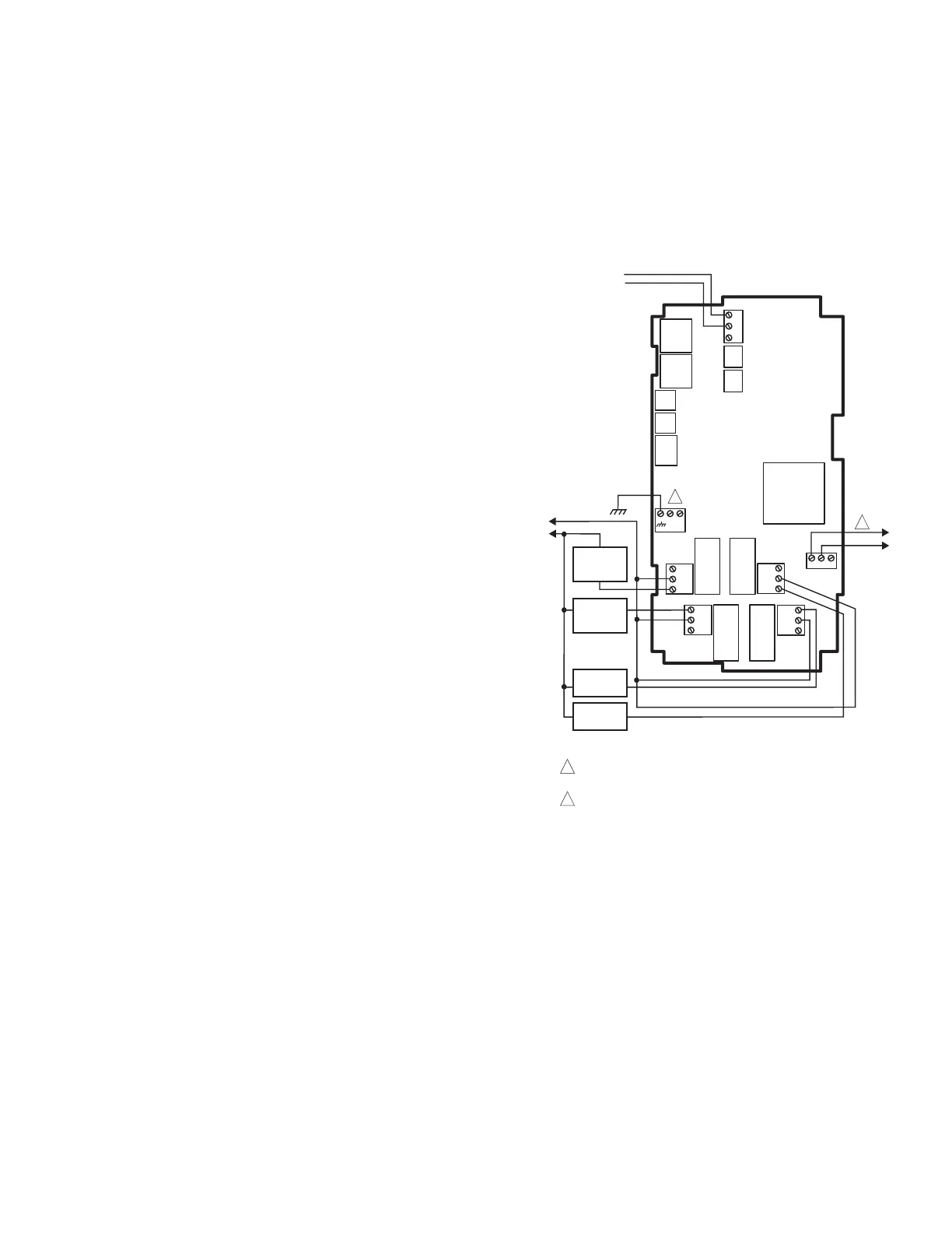
Wiring
All output relays should have a common power wiring source,
which may or may not be the same as the T775 power wiring.
See Fig. 4.
Fig. 4. T775B wiring — chiller.
L1
(HOT)
L2
M24864
SENSOR A
(SUMP WATER)
C
NO
NC
C
NO
NC
C
NC
NO
C
NC
NO
T
T
RELAY
1
FAN
#2
FAN
#1
C
+
SPRAY
PUMP
VALVE
RELAY
4
RELAY
3
RELAY
2
T775B
SUMP
DUMP
VALVE
120
COM
240
POWER WITH 24 VAC OR 120/240 VAC AT THE APPROPRIATE
TERMINAL BLOCK.
24 VAC POWER TERMINAL BLOCK.
1
1
2
120 VAC
2
 Loading...