T775 SERIES 2000 ELECTRONIC STAND-ALONE CONTROLLERS
63-7147—05 12
Time-based Control of Fan, Pump,
etc.
— T775 (all models)
Application Description
In this example, the T775B is able to energize a fan, pump,
lights, economizer, or other device based on a daily time
schedule rather than based on temperature.
Operation
In this example, one relay will energize at 6:00 a.m. and de-
energize at 6:00 p.m. daily to operate a fan, pump, or anything
at all.
Configuration Example
Place a 1,000 Ohm resistor at Sensor B (to simulate a
constant 32° F (0° C) temperature reading).
Wire the device to the normally open contacts on a relay.
Relay 1 is used in this example. See Fig. 7
Programming Example
Program in Setup for:
— Outputs
Options
Use Scheduler = YES
Program in Schedule for:
— Options
Set Date = current date
1
Set Time = current time
Set Daylight = YES or NO
— Mon-Fri
E1 Setpoint = Setpoint
E1 Time = 06:00 AM
E2 Setpoint = Setback
E2 Time = 6:00 PM
Relay 1: Control the device (fan, pump, etc.)
Program for:
— Setpoint = 0° F (-17° C)
— Differential = 1° F (-17° C)
— Sensor = Sensor B
— Setback =100° F (38° C)
— Action = Cool
Now the relay will close at 6:00 a.m. and open at 6:00 p.m.,
daily.
1
The date must be set before the time is set.
NOTE: Keep in mind that if the scheduler is energized, all
relays will follow the time schedule. If you do not
want some outputs to go into a setback mode,
choose Scheduler = NO for those outputs, or
program the setpoint and setback to the same
temperature.
IMPORTANT
After the desired value is selected, be sure to press
the or or HOME button in order to save that
value in the controller’s memory.
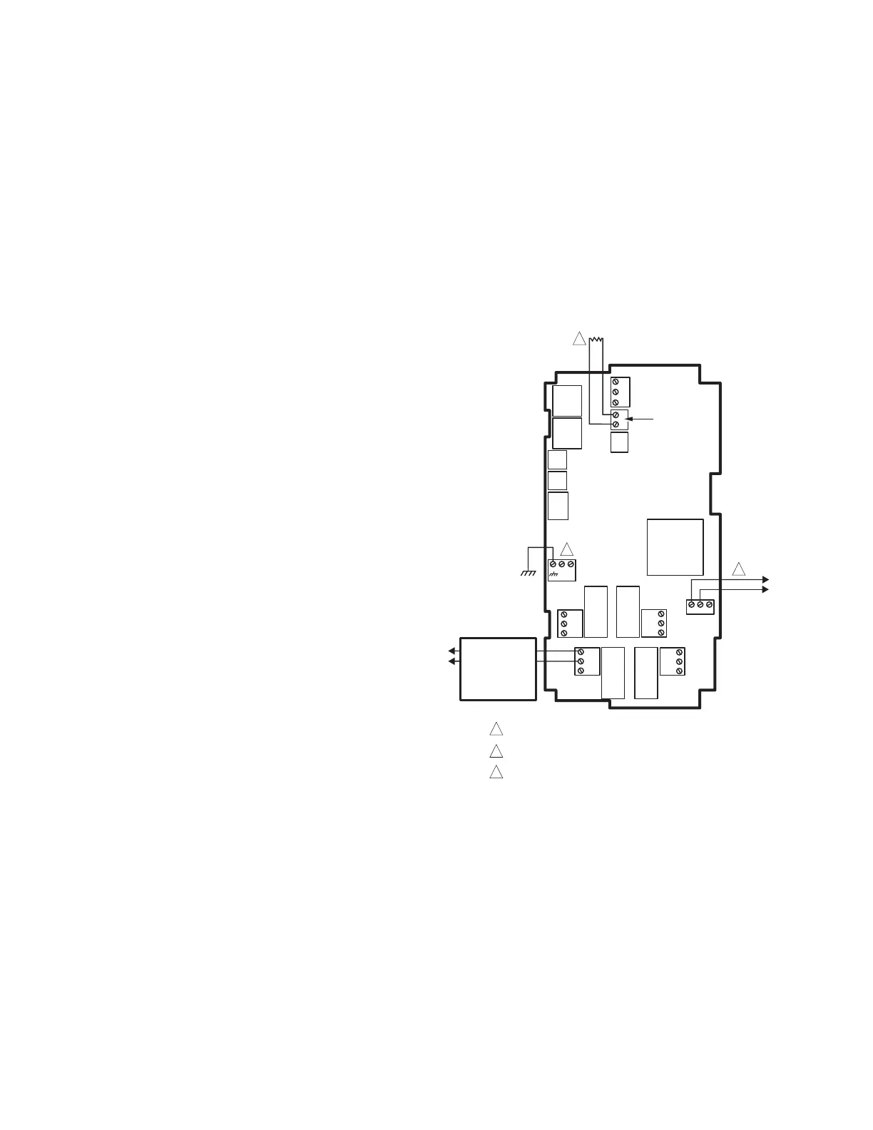
Wiring
All output relays should have a common power wiring source,
which may or may not be the same as the T775 power wiring.
Fig. 7. T775B wiring for time-based fan, pump or other
device.
M28021
T775B
C
NO
NC
C
NO
NC
C
NC
NO
C
NC
NO
T
T
120 VAC
C
+
RELAY
3
RELAY
2
RELAY
1
RELAY
4
120
COM
240
SENSOR B
T
T
FAN,
PUMP,
LIGHTS,
ECONOMIZER,
OR
OTHER DEVICE
L1
(HOT)
L2
1
1
INSERT 1000 OHM RESISTOR.
3
2
24 VAC POWER TERMINAL BLOCK.
POWER WITH 24 VAC OR 120/240 VAC AT THE APPROPRIATE
TERMINAL BLOCK.
3
2
 Loading...