Table 5-17 RJ-45 door description and part number
Description Spare part number
RJ-45 door, ceramic white, RTX models M62233-001
RJ-45 door, shadow black, GTX models M62234-001
RJ-45 door, shadow black, RTX models M75755-001
Before removing the RJ-45 door, follow these steps:
1. Prepare the computer for disassembly (see Preparation for disassembly on page 31).
2. Remove the bottom cover (see Bottom cover on page 31).
3. Remove the battery (see Battery on page 32).
4. Remove the solid-state drives (see Solid-state drive on page 34).
5. Remove the power connector cable (see Power connector cable on page 38).
6. Remove the heat sink (see Heat sink on page 39).
7. Remove the fans (see Fans on page 41).
8. Remove the system board (see System board on page 45).
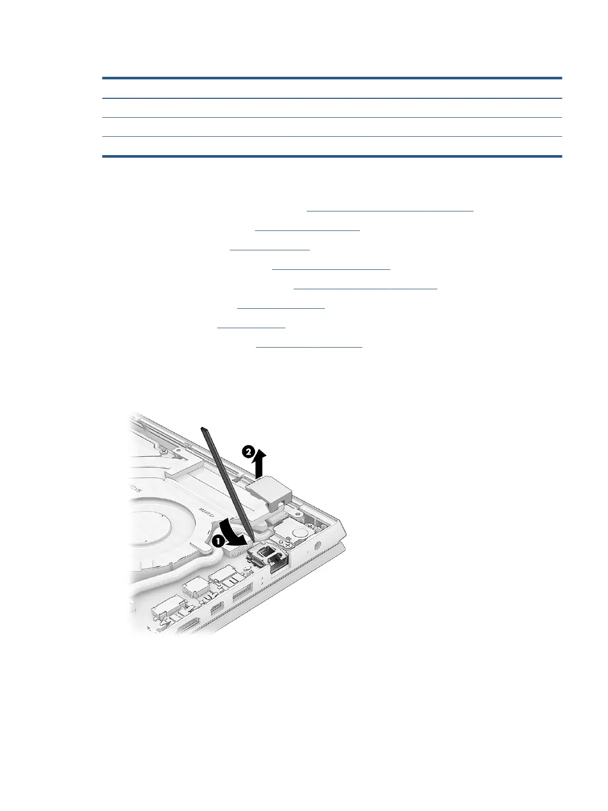
Remove the RJ-45 door:
▲ From the inside of the computer, insert a at tool under the RJ-45 door (1), and then lift the door up to
remove it (2).
Reverse this procedure to install the RJ-45 door.
Display assembly
To remove and disassemble the display assembly, use these procedures and illustrations.
Component replacement procedures 53
 Loading...