Section lll
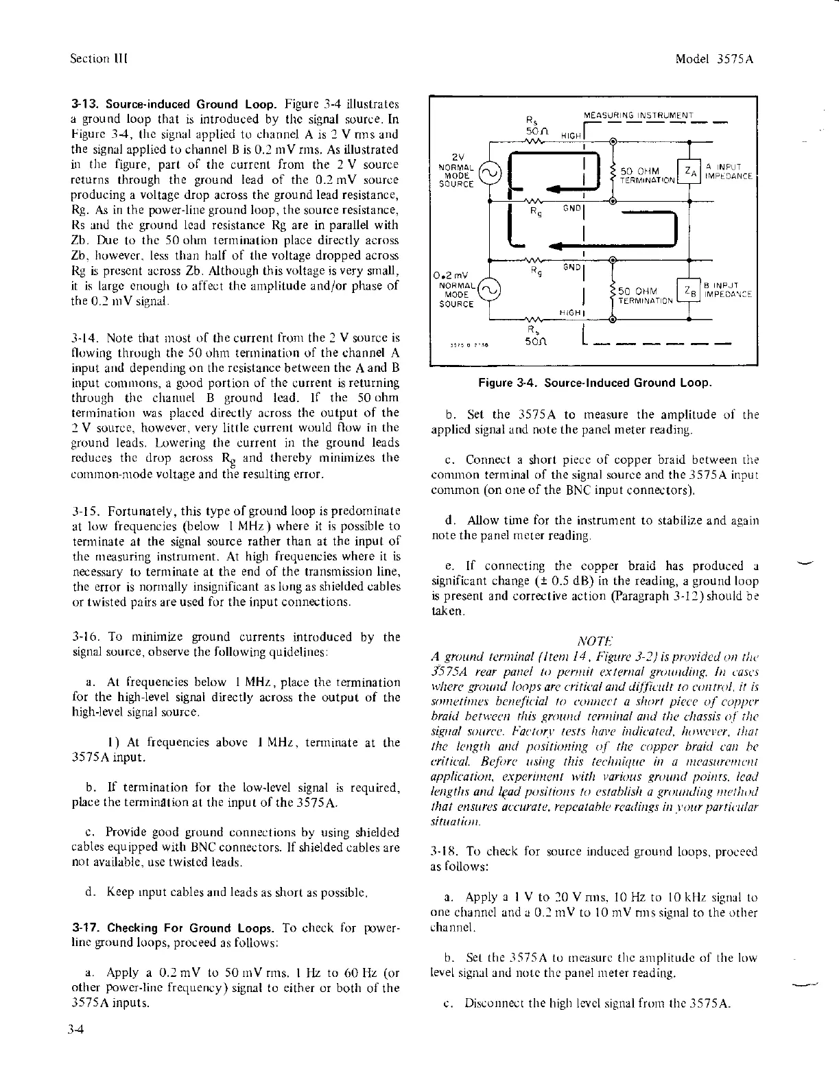
3-13. Source-induced
Ground Loop.
Figure 3-4
i.llustrates
a
ground
loop
that is introduced by tllc signal source. [n
Figurc 3-1,
the signal applicd to channel A is I V nns and
the siSnal applied to channel B is
0.1
mV rlns.
As illustrated
h the
figure, part
of thc currcnt from
the
2 V
source
returns
through the
ground
lead of the 0.2 mV source
producing
a voltage drop
across
the
ground
lead resistance,
Rg.
As in the
power-line ground
loop, the
source
resistance,
Rs
and the
ground
lcad resistance
Rg are in
parallel
with
Zb. Due
to
thc 50 olun terminatior
place
directly across
Zb. howeycr. less than half of the voltage dropped across
Rg is
present
across Zb. Although this
voltage
is
very
small,
it is largc crlough
to affeot
thc
amplitude
and/or
phase
of
the 0.1 rnV signal.
-l-14.
Note that r)rost
(,f
the currert
from
the 2
V
source is
flowing
through the 50 ohm tennination of the channel A
input and depending
on
the
rcsistance
betwcen
the
A
and B
input conl
lons,
a
good portion
of
the
current
is returning
through
thc
chanuel B
ground
lcad. lf the 50
ohm
ternrination
was
placcd
directly across the
output of the
2 V source, howevcr,
very
little current
would flow in the
ground
leads. Lowering the current in
the
ground
leads
rc,lu;c: tlrc tlrop
rcross
\
:rnrJ thercbl rninirDi/cs llre
c()rrtlnon-
lodc
voltage
and
llre resullinS cIlor.
l-15. Fortunately,
this type of
ground
loop is
predomirate
at
low lrequencies
(below
I
MHz)
where it
is
possible
to
tenrinate at the signal source
rather
than
at the input of
the
nreasuring instrunrent.
At
high
frequencies where
it is
nocessrry
to
terminate at the
end
of the transmission
line,
the
error
is
normally insignificant asir.lngas shielded cables
or twisted
pairs
are used for the input connections.
3-16. To midmize
ground
ourrents introduced
by the
signal source. observe
the
following
quidelines:
a. At
frequencies
below I MHz,
place
the
termination
for
the high-level
signal directly across the output of
the
highJevel
signal source.
l) At
frequencies
above I MHz. tenninate
at the
3575 A input.
b. lf ternination for
the
low-level
signal is required,
place
the termination
at the input of the 3575A.
c. Provide
good ground
connections by
using strielded
cables equipped
with BNC connectors.
If shielded cables
are
not
aYailable, use twisted
leads.
d. Keep
rnput cables
and
leads
as short as
possible.
3-17. Checking For
Ground Loops. To check
for
prwer-
linc
ground
loops.
proceed
as
follorvs:
a.
Apply a 0.1 mV to 50 nrv rms.
I [Iz
to
60 Hz
(or
other
powcr-line
frequency)
signal to either or both
of the
3575 A inputs.
34
Model 3575 A
Figure 34.
Source-lnduced
Ground Loop.
b. Set
thc
3575A to
rneasure
the amplitude ol the
applied
signal
and note the
panel
meter reading.
c.
Connect
a
short
piecc
of copper braid bctween rhe
conunon
terminal of the sigrul source and the 3575A input
common
(on
one of
the BNC
input
connectors).
d. A.uow time
for
the instrument to stabilize and acain
note
the
panel
meter
reading.
e.
If connecting the copper braid has
produced
a
significant change
(t
0.5
dB)
in
the reading,
a
ground
loop
is
present
and corrective action
(Paragraph
3-12) shouid be
tatr en.
NOTII
A
gnrund
tenllinol
(ltent
11, Fipra
3-2)is
proyidetl
ort tltt'
J57-5A rear
pancl
to
parnit
axtanwl
gruualing.
In tast,s
wlrcrc grourtd
knps
arc
LritiLal attd dilliL\tlt Io
cr tol,
it i\
sotltatinrcs bctteficial to
qD|tc('t q
sht)rt
piecc
ol cLtytptr
braid ltetwcc'rt tltis
grolutd
tcrttitul
akl
tltc
cltossis o.l
tltc
signol
sourcc.
1"0(tur.t'
tests ltoya in.licotctl, ho\r'crcr, tltat
tllc lc
gtlt
and
positio
ing ol tlrc u)ppcr braid
L'an hc
rritical.
Bj,,ri
rttittg
tltis lc.-lutitluc itt ,t
tttoyrrttttittt
appli('dtio
,
exparifirc
t ttitlt vorioLts
gruutul poi
ts, lcaLl
latlgths
arul
l€sd
pt,sitio
s to cstoblislt a
gnwncliug
rttctltLtl
llwt e surcs ouuratc, repcatahl( rcaLlittgs in
.t'ut
porticular
sitLtatiolt-
3-18.
To check
for
source
induced
ground
loops.
proceed
as follows:
a.
Apply
a
I V
to l0 Vnus. l0 Hz to l0 kllz sigrul to
one
channcl and u 0.1 mV to l0 nlv nns sienal to the other
cha nnel
b.
Set the
-1575A
to rneasurc tlle xmplitudc of the lorv
level signal and llotc ths
panel
meter reading.
c. Disconnect the higl) levcl signal lrorrr lllc 3575A.
50n
MEASL]R
NG N STRUM ENT
2V
M ODE
O.2
mV
MOOE
souRcE
PEOA\'E
R!
s0n
)[l
50
oirM
a
6N0
R9
GND
)
l
50 oHrv l,
-la
9l
v
 Loading...


