Model
35 75 A
this case. the distortion
is at
it's
peak
amplitude when the
fundarnental
is ar the zero
c.ossing
point.
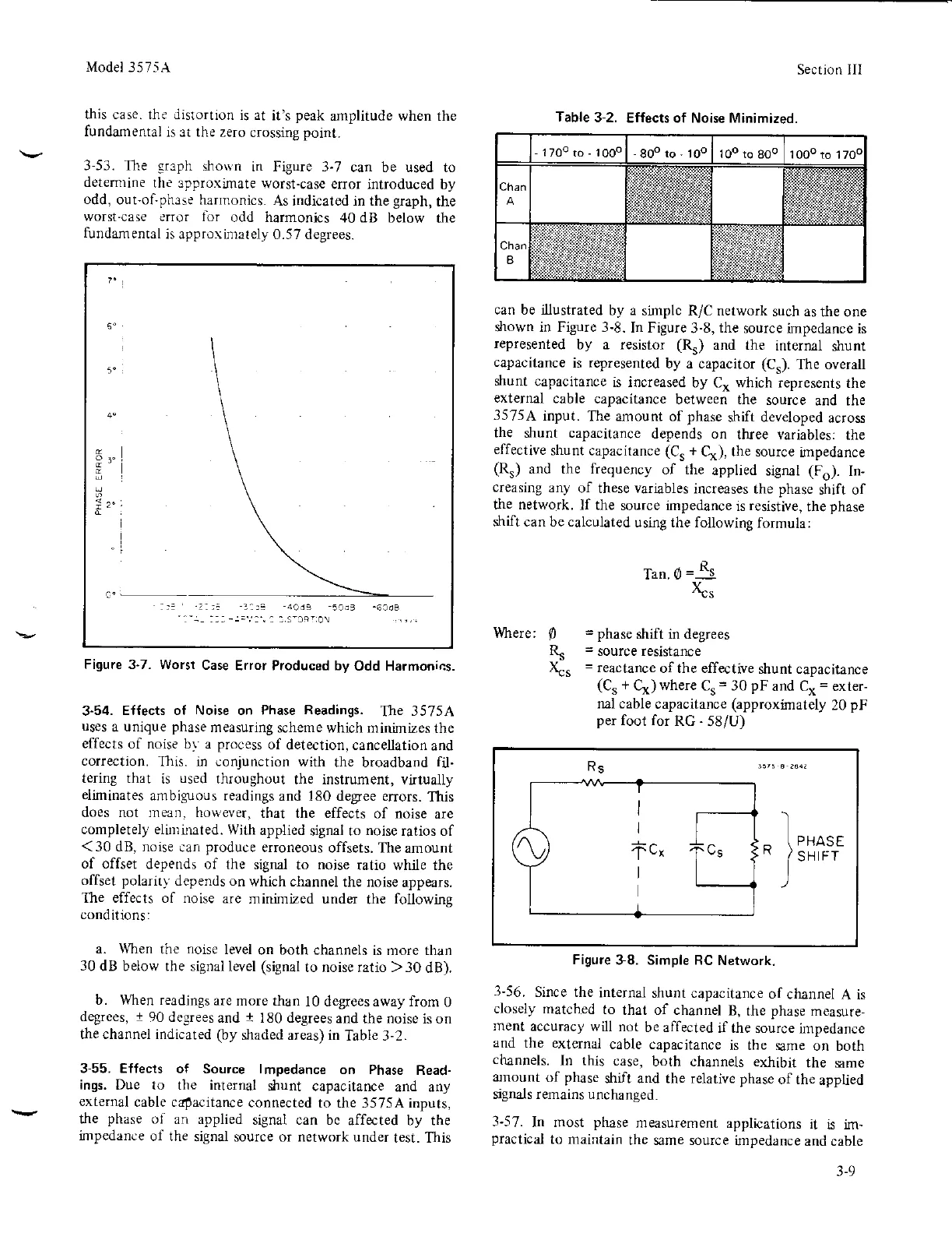
3-53. The
graph
shosn
in Figure 3-7
can be used to
detemrine
the 3pproximate
worst-case
error introduced
by
odd,
out-ol-phase harmonics.
As indicated in the
graph,
the
worst-case error lor
odd harmonics
r10
dB below
the
fundamental
is appro\imately
0.57 degrees.
1z'
Figure 3-7. Worst
Case
Error Produced by
Odd Harmonics.
3-54.
Effects oI Noise on Phase
Readings.
The
35754
uses
a
unique
phase
measuring
scheme which minimizes
the
effects
of noise b) a
process
of
detection, cancellation
and
correction.
This. in conjunction
with
the broadband
fil-
terin8 that
is
used
throughout
the instrument, vttually
eliminates
ambiguous readings
and 180 degree errors.
This
does not mean. however,
that the effects
of noise
are
completely eliminated.
With
applied
sigral to
noise
ratios of
< 30 dB. noise
can
produce
erroneous
offsets.
The amount
of offset
depends of
the signal
to
noise
ratio while the
offset polarit)'
depends on
which
channel the noise
appears.
The effects of noise
are
minimized under
the
following
conditions:
a. When
the
noise
Ievel
on both channels is mo.e than
30
dB beiow the signal
leyel
(siSnal
to noise ratio >30
dB).
b. When readings
are
more than
l0 degrees away from
0
degrees,
t
90 decrees
and
I
180 degrees
and
the
noise
is on
the channel indicated
Oy
shaded areas) in
Table 3-2.
3-55. Effects
of Source lmpedance
on Phase
Read-
ings.
Due to the internal
shunt capacitance
and any
external
cable capacitance
connected
to the 3575A inputs,
t}Ie
phase
oi
an applied
signal can be
affected by the
impedance
of the
signal source or network under
test. This
Section III
can be illustrated
by a
simplc R/C network
such as
the ole
shown in Figure 3-8.
In Figure
3-8,
the
source
impedance is
represented
by a resistor
(Rr)
and the
internal
dlunt
capacitance
is
represelted
by a capacitor
(Cs).
The overall
shunt
capacitance
is increased
by C, which represents
the
external
cable
capacitance
between the
source
and the
35754
input.
The amount of phase
shift developed
across
the
shunt capacitance
depends on
three
variables: the
effective
shunt capacitance
(Cs
+
Cr(), the source
impedance
(Rr)
and the frequency
of the
applied
signal
(Fo).
In-
creasing
any
of these variables
increases
the
phase
shift of
the network.
If the
source impedance
is
resistive,
the
phase
shift can be calculated
using the following
formula:
llhere:
Tan. 0 =
Rs
x^-
=
phase
shift in degrees
=
source resistance
=
reactance
of the effective
shunt capacitance
(Cs
+
Cx)
where
C,
=
30
pF
and Cx
=
exter-
nal cable
capacitance
(approximatety
20
pF
per
foot for
RC
-
58/U)
Figure
38. Simple RC
Network.
3-56.
Since the
internal
shunt capacitance
of
channel
A is
closely matched
to
that of channel
B,
the
phase
measure-
ment
accuracy
will not
be alfected
if the
source impedance
and
the external
cable capacitance
is the same
on both
channels.
In this
case,
both channels exlibit
the same
amount
of
phase
shift and the relative phase
of the
applied
signals remains unchanged.
3-57.
In most
phase
measurement
applications
it
is im-
practical
to maintain
the same source impedance
and cable
0
R^
&.
Table
3-2.
Effects of Noise Minimized.
17oo ro
-
1 ooo
R5
I
I
tc,
I
Ce
-
lrro..
H
J
sHtrr
3-9
 Loading...


