Section IV
gates (A5lC3A,
lCiB). Each OR NOR
gate
splits the
phase
of the ircoming
signal and
provides
trvo outputs that
are
equal in
amplitude and lE0 degrees out of
phase.
These
outputs
are used to trigger
the
two J-K
flip flops
(lC7A,
ICTB)
that
sewe
as
phase
detectors and are also applied to
the
[rror
Conection
Circuirs (IC.1
through
IC6) which
are
discussed in Paragraph 1-55.
The
upper J-K llip
flop, IC7A,
is
"set"
by a
positive
transition oll A
at
the
"J"
input and
"rcsct" by a
positive
transitiorr on B'
(sa]ne
as
a negative
transition on
B) at the
"K"
input. The lorvcr
J'K
flip flop,
lC7B, is
"set
by a
positivc
transition A'(sarne as a
negative
transitior or1 ,{) at the
J
inpul and
"reset"
by a
positive
transition on
B at
the K"
input. The outputs
of
the two
llip flops.
designated Pl. Pl'. Pl and Pl', rcspectiycly. are
applied to
differential amplifiers
IC8B
and lC8A. The
diffcrential
anrplifiers
gate
orr rnd
gatc
off two constaot
current sources
(also
designated Pl and PJ) which
srpply
0urrcnt to the following
ljuffer/lntegrator stage
(l(19).
The
Iluffer/lltegrator scrvcs
3s
an impcdance
converter, an
ilvcrtcr and a high frequency
integrator
(note
that
A5C1
is
oniy 0.1 pl-).
The average
value
of
the pulse train
at
the
outpul of the BLrifer/lntegrator is
proportional
to
the phase
difference belween
the two input signals, A
and
B.
4-16. Wlen
gated
oo, the
Current Sources,
P1 and P2, each
supply 1 mA to the
Buffer/[ntegrator. Due to the
180.1
olun feedback
resistance
(A5Rl3)
ol the Buffcr/
lntegrator, a
I
mA input
current
produces
an output
of
Model .15
75
A
-
1.8 volts-
With
both current sources on. the
sutn olthe
input
currents in I mA and the resulting
output is
-
3.6
volts.
4-27.
Frgure.l-l shou,s thc two limitcd input
sigmls
(A
and
B), the outputs of thc two J-K flip
flops
(Pl
and P2)
and
the rcsultirlg
pulse
train (0)
at the
output
of the
Buffer,/
lntcgrator. ln Figure
.1-1,
the
phase
difference between
A
and
B is
+
60 degrees
(B
ieads A) and the average value
,ri
the
pulse
train i11 the output of the Buffer/lntegrator
is
-
I I volts
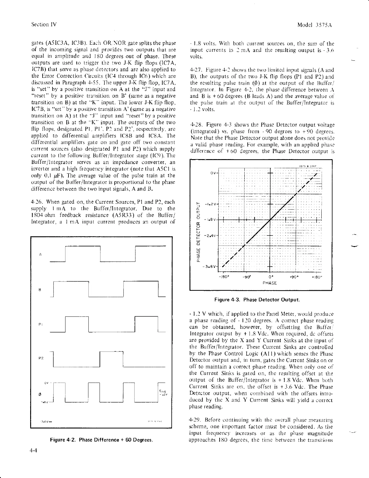
+18.
Figure 4-3 shorvs the Phasc Detector output voltage
(intcgrated)
vs.
phase
from
-
90
degees to
+90
degrees.
Note
that the Phase Detector output
alone does not
provid!,
a valid phase
reading.
For
exarnple,
with an applied
phasc
differencc of
+60
degrees. tiie Phase Detector outpLlt is
Figure 4'3. Phase Detector
Output.
-
1.1
V which.
if
applled to the Panel \1eter. would
produlre
a
phase
reading of
'
ll0
degrees.
A
correct
phase
readinu
can be obtained. however.
by
offsetting
thc Buflcr,
lntegrator output
by
+
1.8 Vdc.
\\ftcn
rcquired,
dc oflsers
are
providcd
by the X and Y
Current Sinks at the input of
the Buffer/lntegrator.
These
Current Sinks are controlled
by the
Phase
Control Logic
(Al
l) which senscs thc Phasc
Dctector
output and, in turn,
gates
the Cu[cnt
Sinks
on or
off to maintain
a
correct pllase
reading. When
oriy one oi
tlie
Current Sioks is
gated
on. thc resulting
ofiset at rhe
output of the
Buffer/lnteqrator is
+
1.E Vdc. When
both
Current
Sinks
are on.
the oflset is
+-1.6
Vdc.
The
Phase
l)etector
output. when combined with
the oiTsets intro,
duced by thc X and Y
Current
Sinks
rvili yield
a correct
phase
reading.
,1"19.
Before corltinuing with tlic overall
phase
measuring
scheme, one il]lportant iaclor
nrust be considered.
As tl)e
input
frequencl
ircreases or as Lhe
phase
rnagnitude
approaches
lilO degrces,
thc tirnc
between
the transitious
t i-
,,: ,/
::/.
/.
o
-."
o
-
3.6V
PEA
SE
4-4
Figute 4-2. Phase
Dif{erence
+
60
Degrees.
 Loading...


