Nlodel
-1575A
4-65. Annunciator Logic
(ABlC4
through
lC6). The
lourth
section of the Function
Switchirlg Assembly
is
the annun-
ciator logic
circuitry. A8lC4 through tC6. This cicuit
roccivcs inputs fronr
the Ap, Bp and Cp
control lincs
and
two additional inputs
tiom
the oyerload detectors on the
Prearnplifier Assemblies, Al and A2. The
purpose
of
the
annunciator
logjc is to control the overload indicators and
the various
lunction
indicators that appear
on
the
Panel
Mcter display.
4-66. 0utput Filter
(A9/A10
Schematic
No.
6).
.l-67.
The Output
Filter is
a
4-pole low
pass filter network
controlled by
the
front parel
FREQUENCY
RANGE
switch. The
purpose
of the filter is to iltegrate
the
arnplitude or
pluse
information before
it is applied to the
Panel Nleter and ANALOG
oUTPUT. The
filter response is
controlled by three
lincs, F, M
and S
which come
from the
Phase
Control
Filter, A7. The Output Filtcr
network is
identical to the Phase Control Filter network
which is
dirussed
in Paragraph 4-34.
-1-(rE.
lt should
l)e noled that lhc
statrdard Modcl
-1575A
which has a
singlc
pancl
meter requircs
ouly oire Output
Filter. This
tllter is dcsign led
A9. l struments thal
rrc
equippcd witlr dtral
palcl
Drcters
(Options
0Ol
00-l)
rcquirc il
scparate
Oulput
Filler for
caclt
pancl
meter and,
thcrcforc.
c{)r1ail both
A9 and Al0 which arc
ideotical.
Since
thc
dual
pxrlel
meter options arc tleid
inslallablc. the
strrrdrrd \lodel
-1575A
has r
vacant
board slot
and
conncclor lo
pernril
thc addition of
Al0.
&69. 0igital
Panel
Meter.
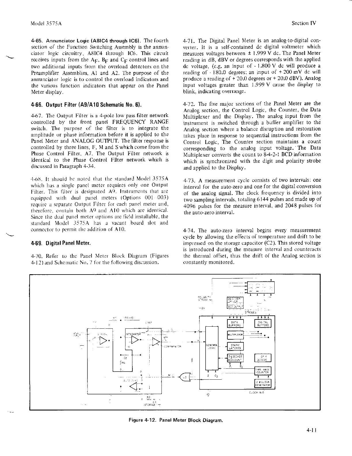
4-70. Refer to thc
Panel X1etcr Block Diagram
(Figures
4-12)and Schenratic
No,
7
lirr the following discussion.
Section [V
1-71. The Digital
Panel Nleter
is an analog-to-digital
con'
verter. It is
a self-contained
dc digital
voltmeter which
measures
voltages between
i
1.999
V dc. The Panel Nleter
reading in dB,
dBV or degrees
corresponds
with the applied
dc voltage,
(e.g.
an
input
of
-
1.800V dc will
produce
a
reading of
-
180.0 degrees;
an input
of
+
200 mV
dc will
produce
a
reading of
+
20.0
degrees or
+
20.0 dBV)' Analog
input voltages
greater
than
1-999V cause the
display to
blink, indicating
oYerrange.
4-72. T\e
five major sections
of the Panel Nleter
are the
Analog section,
the
Control
Logic, the
Counter, the
Data
lUultiplexer
and the
Display.
The analog
input from
the
instrument
is switched
through
a buffer
amplifier
to the
Analog seotion
where a balance
disruption
and
restoration
takes
place
in response
to sequential
instructions
irom
the
Control l-ogic,
The Counter
section
maintains a count
corresponding
to the analog
input
voltage. The
Data
Illultiplexer
converts the counl
to 8-4'2-l
BCD information
which is synchronized
with fie digit and
Polarity
strobe
and applied
to the
Display,
4-73. A nreasurement
cycle
consists of two intervals:
one
interval for the auto-zero
and
one
for the
digital
conversion
oI the analog
signal.
The clock
frequency is divided
into
two sampling
intervals,
totaling
6144
pulses
and made
up of
4096
pulses for the measure interval,
and 2048
pulses
for
the
auto-zero
interval.
1-14.
The auto-zero
interval begins every
measurement
cycle by allowing
the elfects
of temperature and drift to be
impressed on the storage
capacitor
(C2).
This
stored
voltage
is introduced during the measure
interval
and
counteracts
the thernul olfset, thus
the
drift
ol the Analog section is
corstantly
monitored,
Figue 4-12. Panel Meter
Block Diagram.
4.1 I
 Loading...


