2-25
Installing the HP 5400 zl Switches
Installation Procedures
Installing the HP 5400 zl
Switches
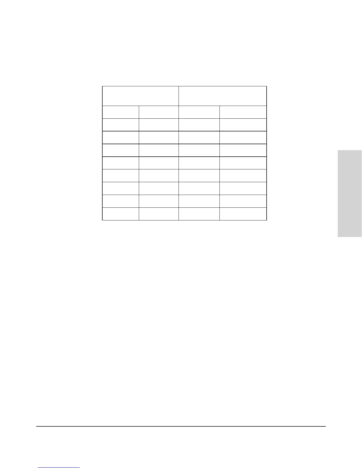
Figure 2-16. RJ-45 to DB-9 pinouts
Table 2-2. Mapping of RJ-45 to DB-9
Telnet Console Access
To access the switch through a telnet session, follow these steps:
1. Ensure the switch is configured with an IP address and that the switch is
reachable from the telnet workstation (for example by using a Ping
command to the switch’s IP address)
2. Start the telnet program and connect to the switch’s IP address.
3. The copyright page and the message “Press any key to continue” will
display. Press a key, and the switch console CLI prompt will display.
If you want to continue with console management of the switch at this time
through either a direct connection or a TELNET session, see chapter 3,
“Getting Started With Switch Configuration” for some basic configuration
steps. For more detailed information, refer to the Management and Config-
uration Guide which is on the HP networking Web site.
RJ-45 (Signal reference from
Chassis)
DB-9 (Signal reference from PC)
Reserved 1 8 CTS
Reserved 2 6 DSR
TXD 3 2 RXD
Reserved 4 1 DCD
GND 5 5 GND
RXD 6 3 TXD
Reserved 7 4 DTR
Reserved 8 7 RTS
9 RI

 Loading...