8
Installing the switch in a 19-inch rack
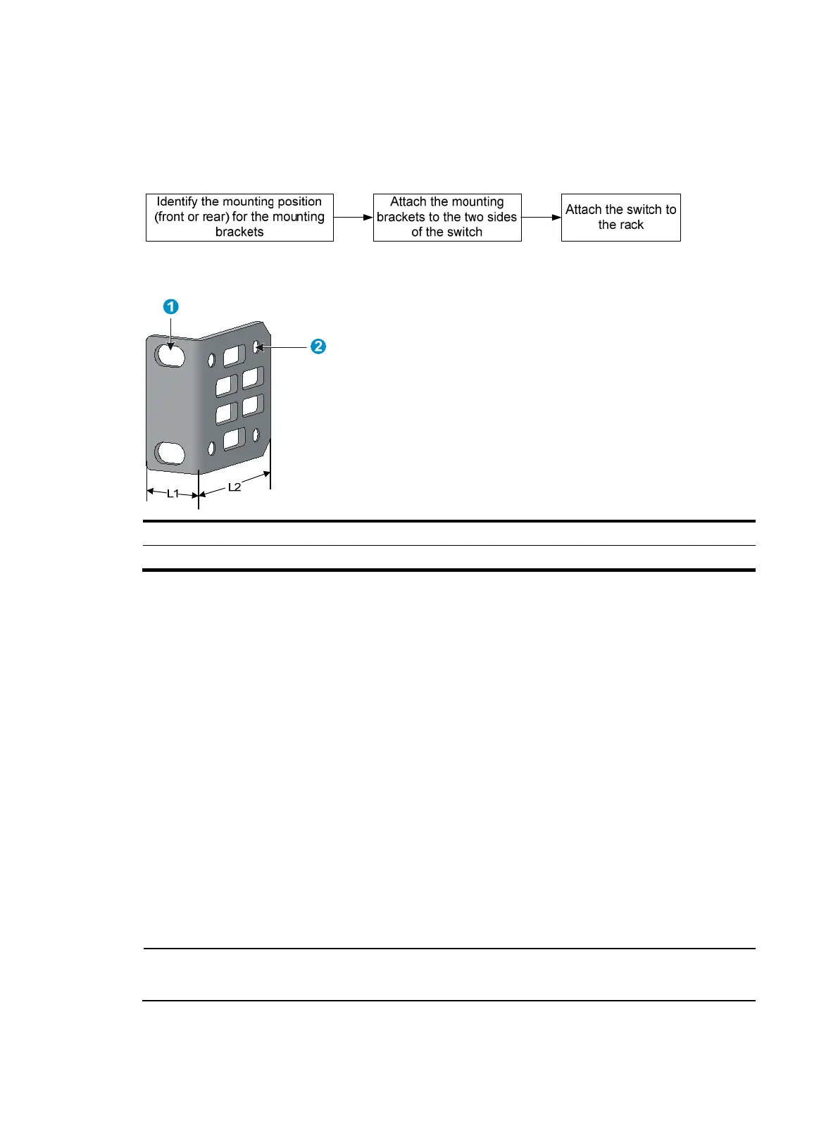
Every A5500 HI switch comes with a pair of mounting brackets (see Figure 7) for rack mounting.
Figure 6 Rack-mounting procedure
Figure 7 Mounting bracket
(1) Hole for attaching to a rack (by using an M6 screw)
(2) Hole for attaching to the switch chassis
Prerequisites
If you are installing an LSP5GP8P0 (JG314A) interface card, make sure the rack depth is 800 mm (31.50
in) or 1000 mm (39.37 in). This card adds 69.75 mm (2.75 in) to the chassis depth (see Figure 24) in
addition to the c
learance required for installing transceiver modules and cables.
Attaching the mounting brackets to the chassis
To attach the mounting brackets to the chassis:
1. Identify the front mounting position (see Figure 8) and rear mounting position (see Figure 9) on the
two sides of the chassis.
2. Align the round holes in the wide flange of one front mounting bracket with the screw holes in the
front or rear mounting position on one side of the chassis
3. Use M4 screws (supplied with the switch) to attach the mounting bracket to the chassis.
4. Repeat the preceding two steps to attach the other mounting bracket to the other side of the
chassis.
NOTE:
The screw holes in the figures in this section are for illustration only.
 Loading...


