Do you have a question about the HP Compaq Elite 8300 Series and is the answer not in the manual?
| Chipset | Intel Q77 Express |
|---|---|
| Memory | Up to 32 GB DDR3 |
| Processor | Intel Core i3/i5/i7 |
| Storage | SSD |
| Graphics | Integrated Intel HD Graphics |
| Optical Drive | DVD-ROM, DVD+/-RW |
| Operating System | Windows 7, Windows 8, FreeDOS |
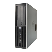
| Form Factor | Small Form Factor (SFF) |
| Audio | Integrated High Definition Audio |
| Network | Integrated Gigabit Ethernet |
| Ports | USB 2.0, USB 3.0, DisplayPort, VGA, Serial, PS/2, Audio |
General overview of features and configurations across different models.
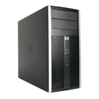
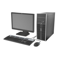
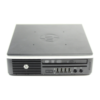
Identifies and describes components on the front of CMT, MT, SFF, and USDT models.
Identifies and describes components on the rear of CMT, MT, SFF, and USDT models.
Identifies and describes the components of the media card reader.
Identifies keyboard components and explains Windows Logo key functions.
Shows where to find the serial and product ID numbers on the computer.
Lists essential safety instructions and precautions before performing upgrades.
Details procedures for removing and replacing the computer's access panel.
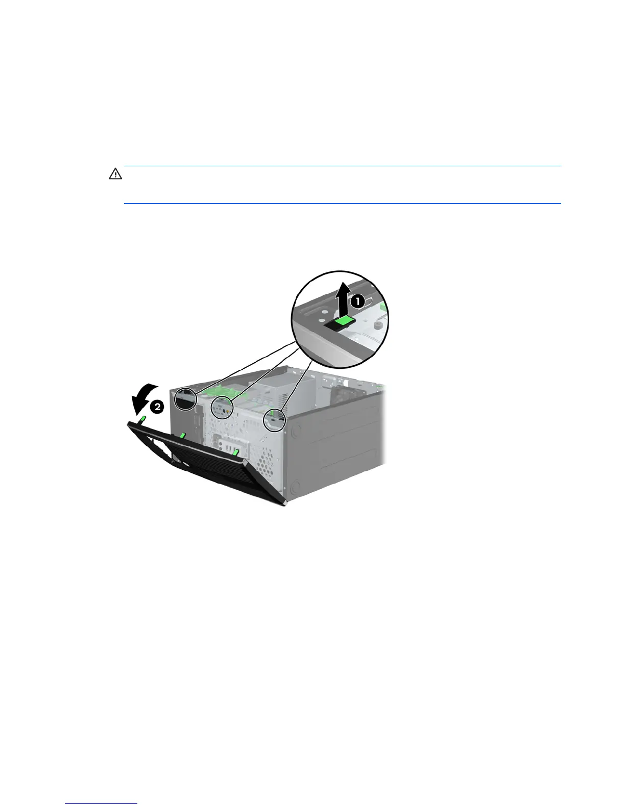
Details procedures for removing/replacing front bezel and bezel blanks.
Identifies and describes the various connectors on the system board.
Provides instructions for installing memory modules, including DIMM types and population.
Details the procedure for installing or removing expansion cards.
Identifies drive bay locations and procedures for removing drives.
Details procedures for installing 5.25-inch drives and internal hard drives.
Explains how to convert the computer from minitower to desktop configuration.
Provides instructions for installing various types of security locks.
Details how to install a security screw for the front bezel.
Lists essential safety instructions and precautions before performing upgrades.
Details procedures for removing and replacing the computer's access panel.
Details procedures for removing/replacing front bezel and bezel blanks.
Identifies and describes the various connectors on the system board.
Provides instructions for installing memory modules, including DIMM types and population.
Details the procedure for installing or removing expansion cards.
Identifies drive bay locations and procedures for removing drives.
Provides guidelines for installing and removing various types of drives.
Details procedures for installing 5.25-inch/3.5-inch drives and internal hard drives.
Provides instructions for installing various types of security locks.
Details how to install a security screw for the front bezel.
Lists essential safety instructions and precautions before performing upgrades.
Details procedures for removing and replacing the computer's access panel.
Details procedures for removing/replacing front bezel and bezel blanks.
Explains how to convert the computer to a tower orientation.
Identifies and describes the various connectors on the system board.
Provides instructions for installing memory modules, including SODIMM types and population.
Details the procedure for installing or removing expansion cards.
Identifies drive bay locations and procedures for removing drives.
Provides guidelines for installing and removing various types of drives.
Details procedures for installing 5.25-inch and 3.5-inch drives.
Provides instructions for installing various types of security locks.
Details how to install a security screw for the front bezel.
Lists essential safety instructions and precautions before performing upgrades.
Provides step-by-step instructions for connecting the power cord.
Details procedures for removing and replacing the computer's access panel.
Details procedures for removing/replacing front bezel and bezel blanks.
Explains how to convert the computer to a tower orientation.
Identifies and describes the various connectors on the system board.
Provides instructions for installing memory modules, including SODIMM types and population.
Details procedures for removing, preparing, and installing the optical drive.
Details the procedure for replacing the 2.5-inch internal hard drive.
Details how to install and remove the optional rear port cover.
Provides instructions for installing various types of security locks.
Details how to install a security screw for the front bezel.
Warns about battery risks and advises backing up CMOS settings.
Describes the procedures for replacing batteries in Type 1, Type 2, and Type 3 holders.
Lists steps to complete after replacing the computer battery.
Advises backing up data before removing or replacing the hard drive.
Details steps for unlocking and removing the hard drive carrier and its cover.
Details steps for removing the hard drive from the carrier and installing a new one.
Informs that the Smart Cover Lock is an optional feature and explains its purpose.
Explains the FailSafe Key's purpose, use cases, and how to obtain it.
Details how to use the FailSafe Key to remove the Smart Cover Lock.
Lists precautions to prevent damage from electrostatic discharge.
Describes various methods for grounding oneself when handling parts.
Advises contacting HP for more information on static electricity.
Provides guidelines for proper setup, operation, and routine care of the computer.
Lists guidelines for operation, cleaning, and safety of the optical drive.
Provides suggestions for preparing the computer for shipping.