23
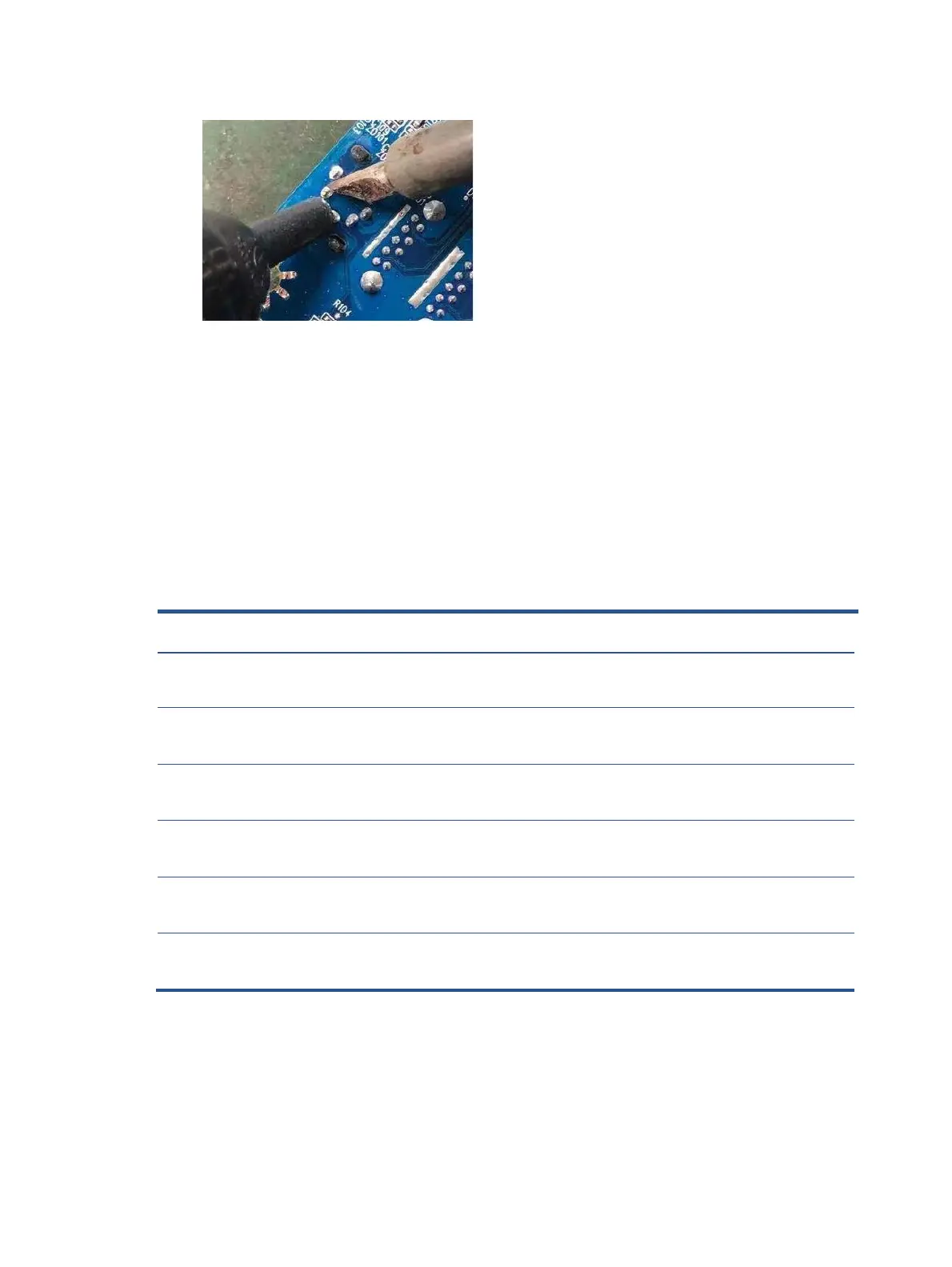
1) Use e a hot air gun to heat the bottom side of PCB below the headphone connector.
Remove headphone connector
2) Lift the CN102 connector from the PCB.
3) Place the new component on the circuit board. Be sure that it matches the footprint.
4) Solder the new component.
Function test
After repair, be sure to confirm that all functions are working.
Support and troubleshooting
The following table lists possible problems, the possible cause or each problem, and the recommended
solutions.
Function test
After repair, be sure to confirm that all functions are working.
Table 4-1: Function test
Confirm whether image displays and sound plays
correctly on the monitor.
Confirm whether image displays and sound plays
correctly on the monitor.
Change volume and balance to confirm whether
volume is smooth and loud enough.
Confirm whether image displays and sound plays
correctly on the monitor.
Confirm whether image displays and sound plays
correctly on the monitor.
Change volume and balance to confirm whether
volume is smooth and loud enough.
Confirm whether transmitting data between
computer and USB devices.
Confirm whether image displays, sound plays and
data transmitting correctly on the monitor.
Confirm whether connecting to the internet
 Loading...