2-11
Installing the Switch
Installation Procedure
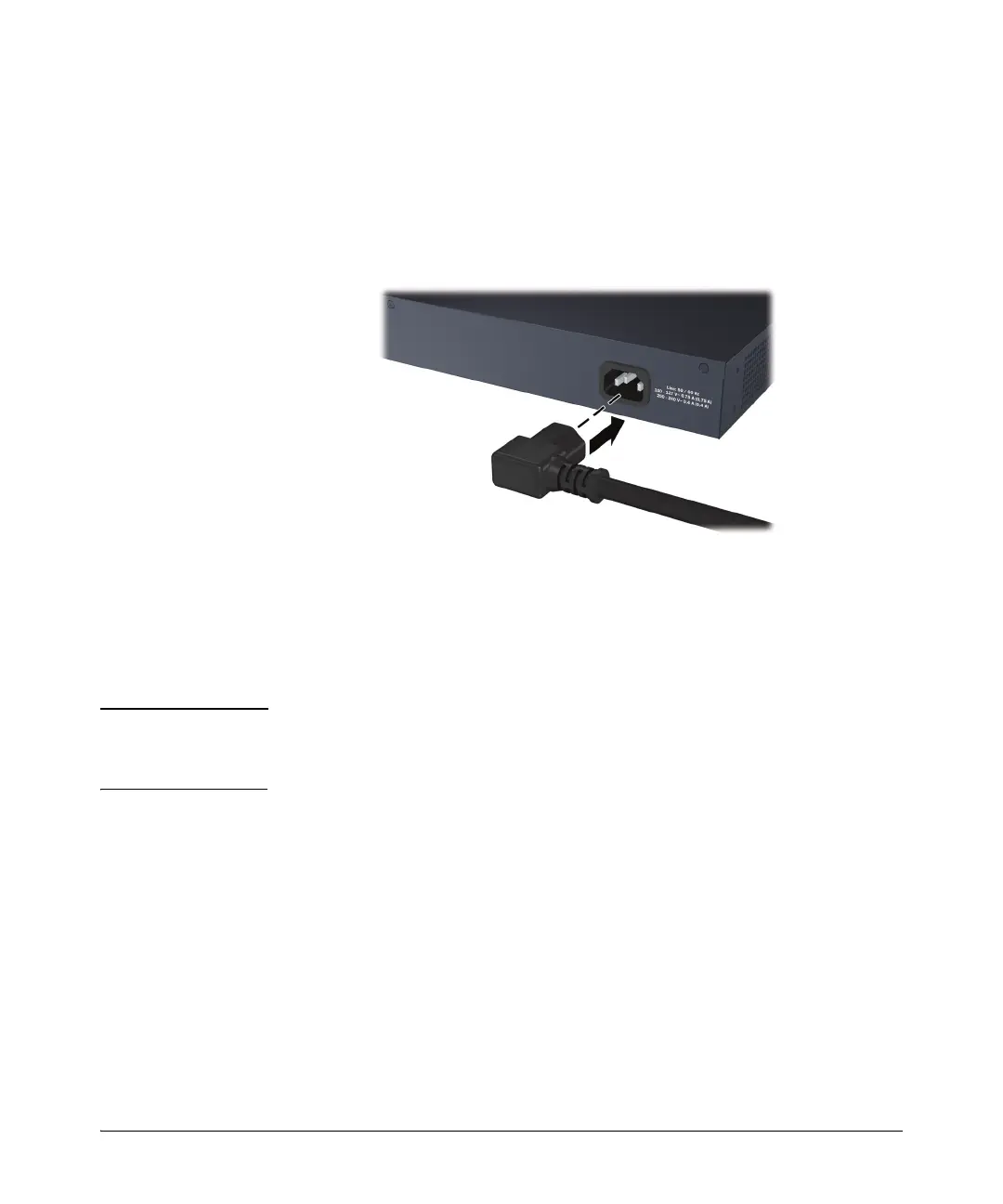
4. Connect the Switch to a Power Source
1.) Plug the included power cord into the switch’s power socket and into a
nearby AC power source.
2.) Re-check the LEDs during self test. See “Self Test LED Behavior” on
page 2-5.
5. Connect the Network Cables
Connect the network cables, from the network devices or your patch panels,
to the fixed RJ-45 ports on the switch or to any mini-GBICs you have installed
in the switch.
Note Each of the two mini-GBIC slots is shared with the associated 10/100/
1000Base-T RJ-45 port. If a mini-GBIC is installed in a slot, the associated
RJ-45 port is disabled.
 Loading...