Hardware options installation 36
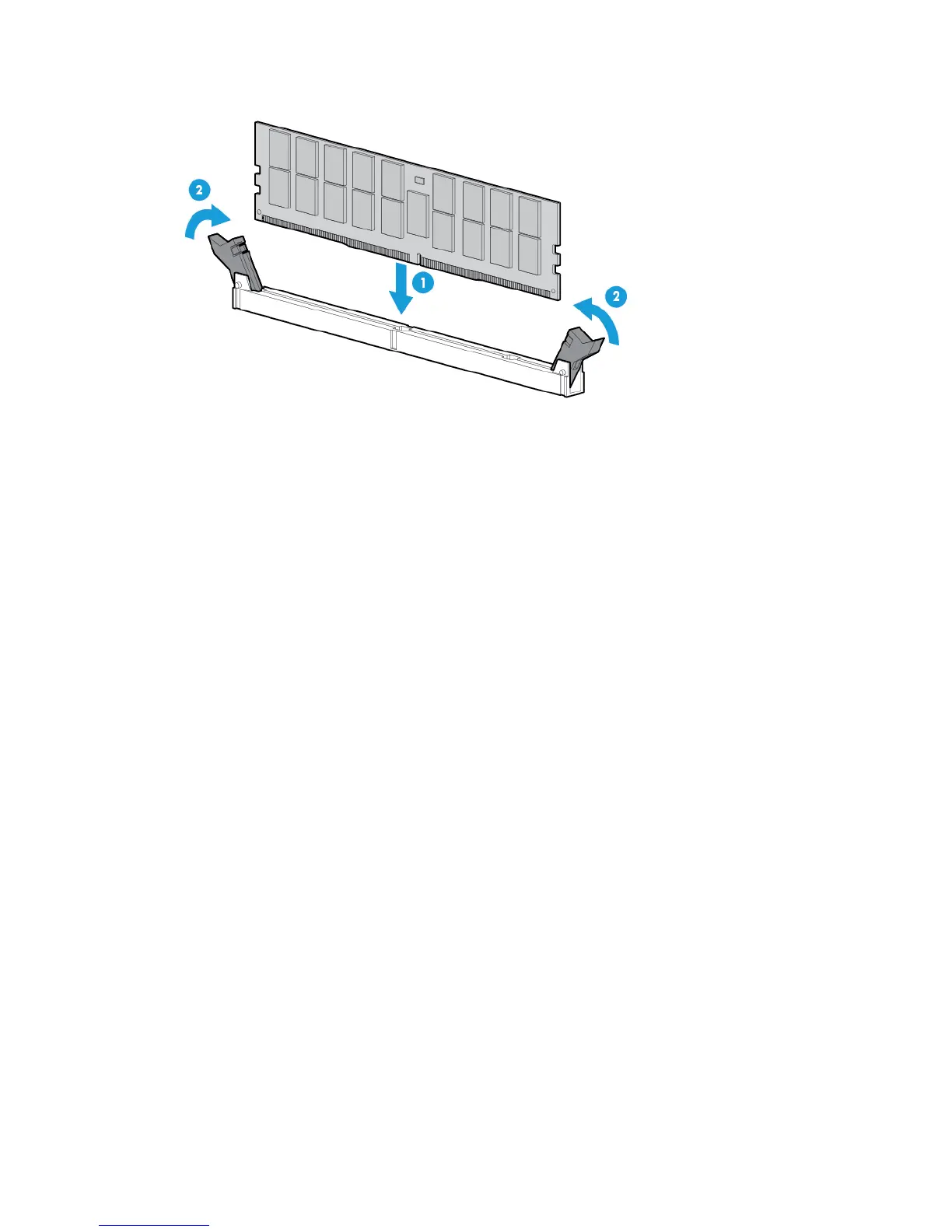
7. Install the DIMM.
8. Install the air baffle (on page 16).
9. Install the access panel (on page 15).
10. Install the tower bezel (on page 13).
11. Connect each power cord to the server.
12. Connect each power cord to the power source.
13. Power up the server (on page 13).
After installing the DIMMs, to configure memory protection mode, use RBSU.
Setting up the HP PS1810-24G Switch (optional)
If you intend to use the server with the companion HP PS 1810-24G Switch, follow the procedures in this
section.
For more information on switch-related settings and operational procedures, see the documentation for your
switch model on the HP website (http://www.hp.com/networking/support).
Mounting the switch with the server
Mount the switch in a rack, on a wall, or on top of or under a horizontal surface. For detailed instructions, see
the HP PS1810-24G Switch Quick Setup Guide.
Connecting the server to the switch
To establish an Ethernet connection:
1. Connect an Ethernet cable to the switch, and then connect the cable to a network jack.
2. Connect an Ethernet cable to the server NIC connector 1 or 2 ("Rear panel components" on page 8).
 Loading...