1. Prepare the computer for disassembly (see Preparation for disassembly on page 33).
2. Remove the bottom cover (see Bottom cover on page 37).
3. Remove the battery (see Battery on page 38).
4. Remove the right solid-state drive (near the WLAN module) (see Solid-state drive on page 33).
5. Remove the heat sink (see Heat sink on page 41).
6. Remove the fan (see Fans on page 43).
7. Remove the USB board (see USB board on page 45).
8. Remove the system board (see System board on page 47).
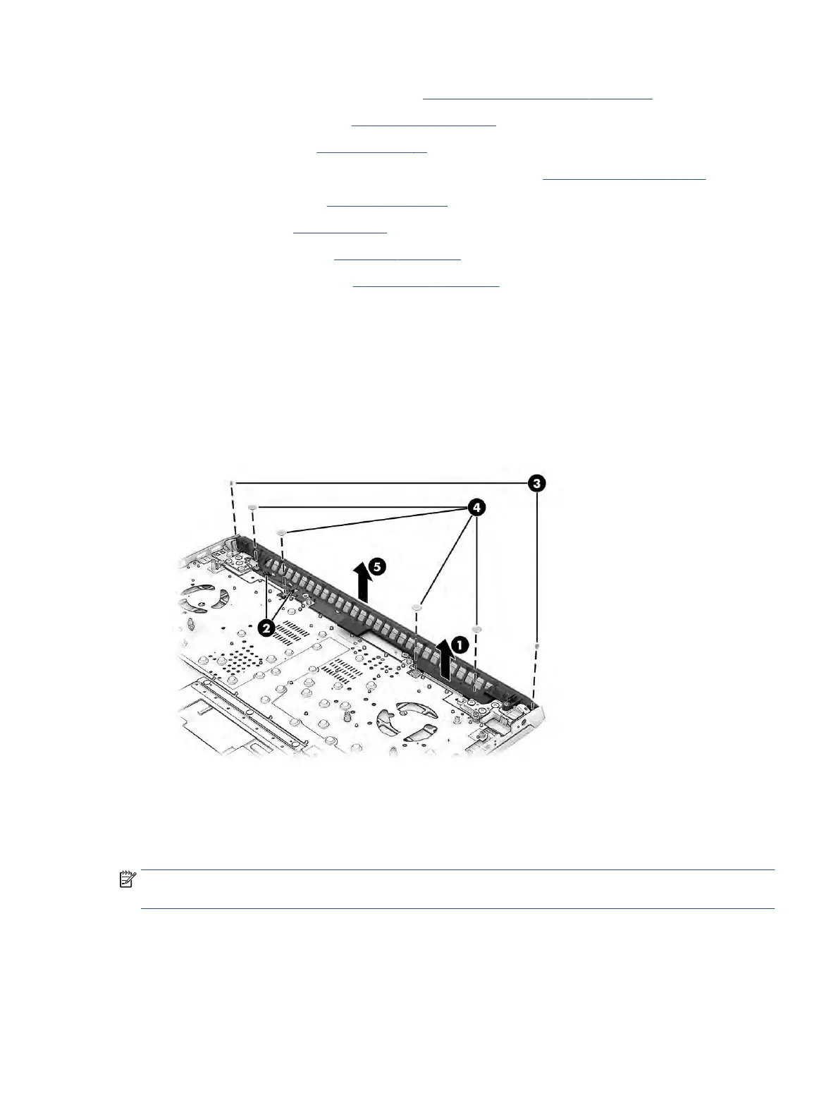
Remove the rear vent:
1. Remove the display cable from the top of the rear vent (1).
2. Remove the WLAN antennas from the tape and the clip (2).
3. Remove the two Phillips M1.6 × 3.0 screws from the top corners of the vent (3).
4. Remove the four Phillips M2.0 × 2.0 screws from the vent (4).
5. Remove the rear vent from the computer (5).
Reverse this procedure to install the rear vent.
Display assembly
To remove and disassemble the display assembly, use these procedures and illustrations.
NOTE: The display assembly is available as a spare part only at the subcomponent level. For display
assembly spare part information, see the individual removal subsections.
Before removing the display panel, follow these steps:
Component replacement procedures 53
 Loading...