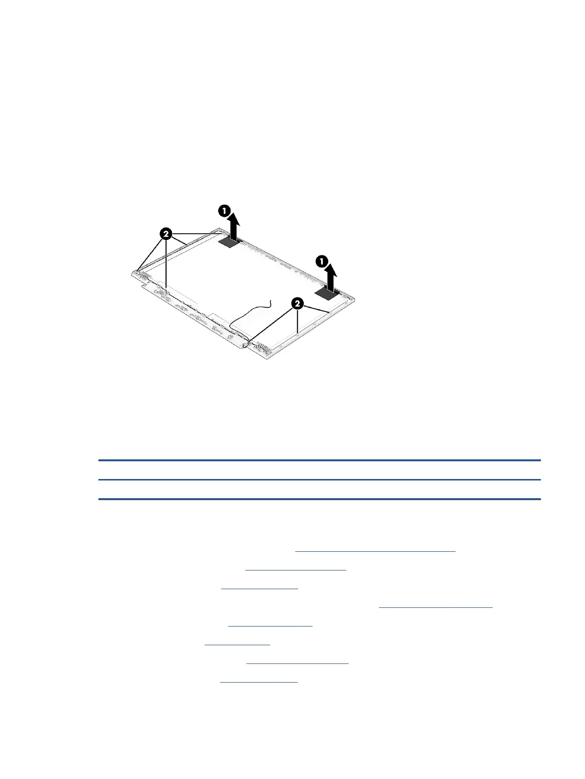
8. Peel the wireless antennas (1) o the display back cover. The antennas are secured with adhesive.
Release the wireless antenna cables from the retention clips and routing channels built into the sides
and bottom of the display back cover (2).
The wireless cables and antennas are available as spare part number M54724-001.
Display back covers are available as the following spare part numbers:
M54721-001: Ceramic white
M54721-001: Mica silver
M54721-001: Performance blue
Reverse this procedure to reassemble and replace the display assembly.
Power connector cable
To remove the power connector cable, use this procedure and illustration.
Table 6-14 Power connector cable description and part number
Description Spare part number
Power connector cable M54715-001
Before removing the power connector cable, follow these steps:
1. Prepare the computer for disassembly (see Preparation for disassembly on page 33).
2. Remove the bottom cover (see Bottom cover on page 37).
3. Remove the battery (see Battery on page 38).
4. Remove the right solid-state drive (near the WLAN module) (see Solid-state drive on page 33).
5. Remove the heat sink (see Heat sink on page 41).
6. Remove the fan (see Fans on page 43).
7. Remove the system board (see System board on page 47).
8. Remove the rear n (see Rear n on page 51).
Component replacement procedures 59
 Loading...