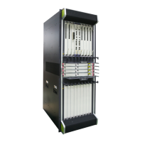
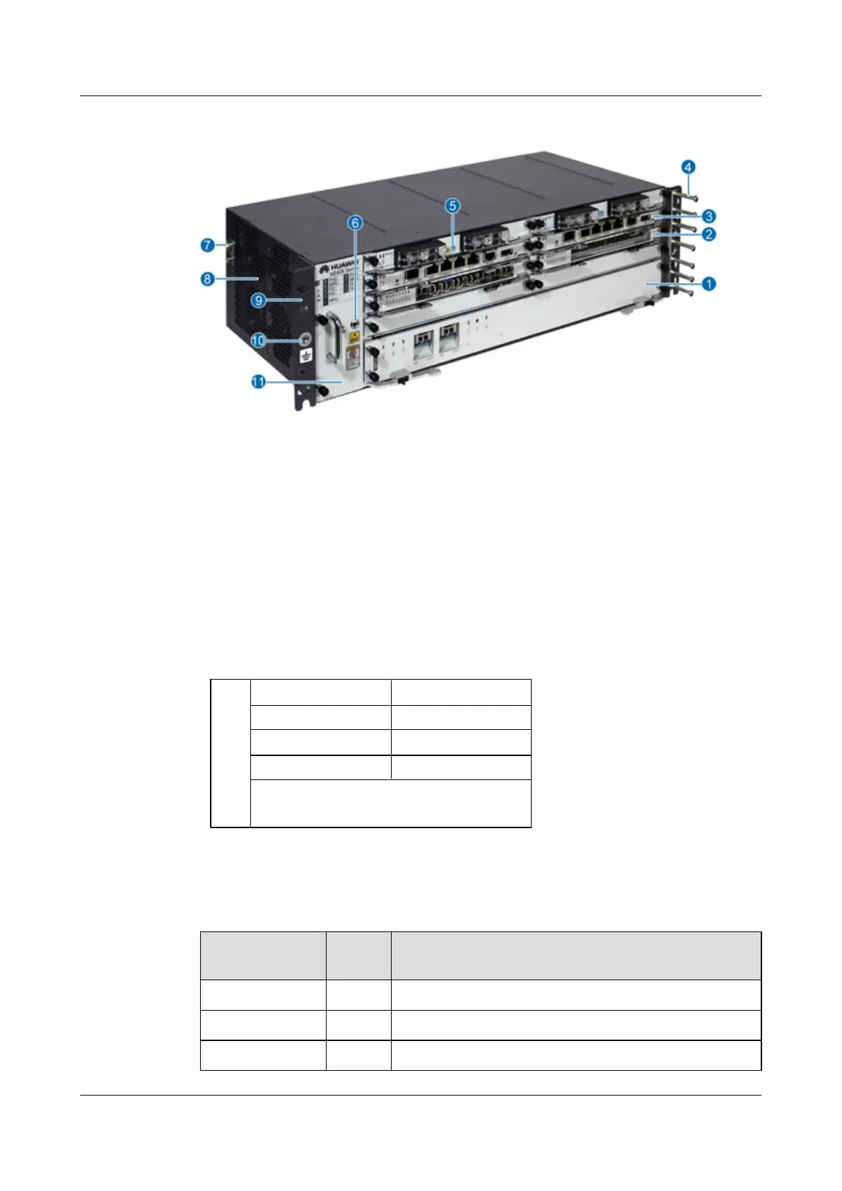
Figure 1-3 Outline and parts of the NE40E-X1
1. NPU 2. PIC 3. MPU 4. Cabling rack
5. PSU 6. ESD jack 7. Grounding Terminal 8. Air intake vent
9. Rack-mounting ear 10. Grounding Terminal 11. Fan module
1.1.6 Number of Main Parts and Slot Layout of the NE40E-X1
Figure 1-4 shows the slot layout of the NE40E-X1.
Figure 1-4 Slot layout of the NE40E-X1
10
FAN
8 PSU 9 PSU
1 NPU
5 FIC/HIC
4 FIC/HIC
3 FIC/HIC
6 MPU 7 MPU
2 FIC/HIC
Table 1-2 Number and layout of slots on the NE40E-X1
Slot No.
Quanti
ty
Remarks
1 1 For NPUs.
2, 3, 4, and 5 4 For sub-cards, which include HICs and FICs.
6 and 7 2 For MPUs, which work in 1:1 backup mode.
HUAWEI NE40E-X1 & NE40E-X2 Universal Service
Router
Hardware Description 1 NE40E-X1 Hardware Description
Issue 02 (2011-09-10) Huawei Proprietary and Confidential
Copyright © Huawei Technologies Co., Ltd.
5
 Loading...