At one end of the alarm input/output cable, the RJ-45 connector is used to connect to the ALMI
or ALMO interface on the equipment; at the other end, a connector (made as required on site)
is used to connect to the external equipment or the equipment that monitors all the alarms.
4.9.2 Structure
Structure
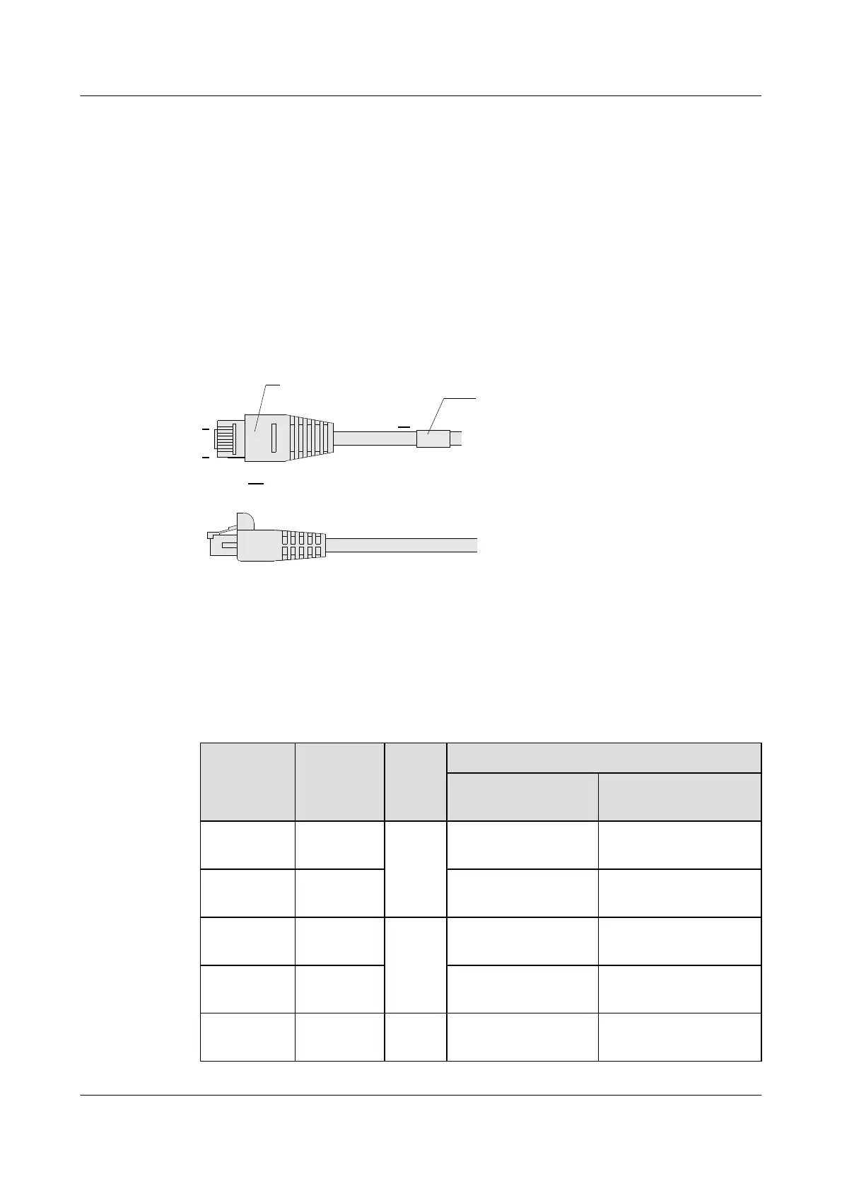
Figure 4-9 shows the structure of the alarm input/output cable.
Figure 4-9 Structure of the alarm input/output cable
W
X1
8
1
RJ-45 Connector
Main label
Pin Assignment
Table 4-21 lists the pin assignment of the alarm input/output alarm cable connector.
Table 4-21 Pin assignment of the alarm input/output cable
Connector
Pin
Color Relati
on
Description
ALMI Interface
Cable
ALMO Interface
Cable
1 White-
orange
Twiste
d pair
Alarm input 1 Positive of alarm output
1
2 Orange Ground for alarm input
1
Negative of alarm output
1
3 White-green Twiste
d pair
Alarm input 2 Positive of alarm output
2
6 Green Ground for alarm input
2
Negative of alarm output
2
4 Blue Twiste
d pair
Alarm input 3 Positive of alarm
concatenation 1
HUAWEI NE40E-X1 & NE40E-X2 Universal Service
Router
Hardware Description 4 Cables
Issue 02 (2011-09-10) Huawei Proprietary and Confidential
Copyright © Huawei Technologies Co., Ltd.
91
 Loading...