Appearance
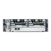
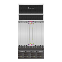
Figure 1-52 shows the appearance of the switch.
Figure 1-52 Switch
Panel
Table 1-56 Switch Description
Controls the device power connectivity.
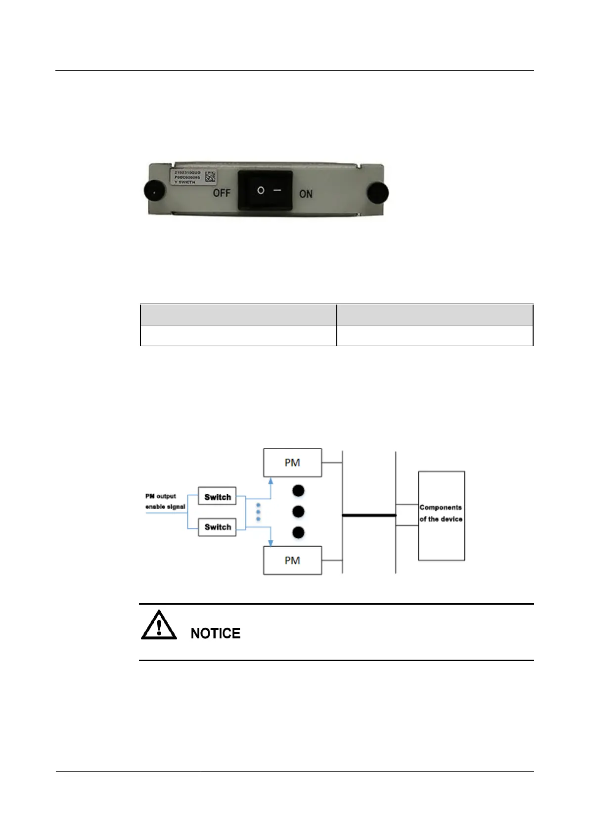
Function
When one or both switches are turned on, the PMs output power, and the device is powered
on. When both switches are turned off, the PMs do not output power, and the device is
powered off.
Ensure that both switches are turned on when the device is running for reliability purposes.
 Loading...