and the two terminals on the left are connected to the power supply plane on the client side.
The AC PEM is fully configured with the entire system. The system has four PEMs.
Appearance
Figure 1-69 shows the appearance of an AC PEM.
Figure 1-69 AC PEM
Panel
Table 1-89 Interface Description
Applicable power cable terminals
Input interface for
220 V AC power
supply
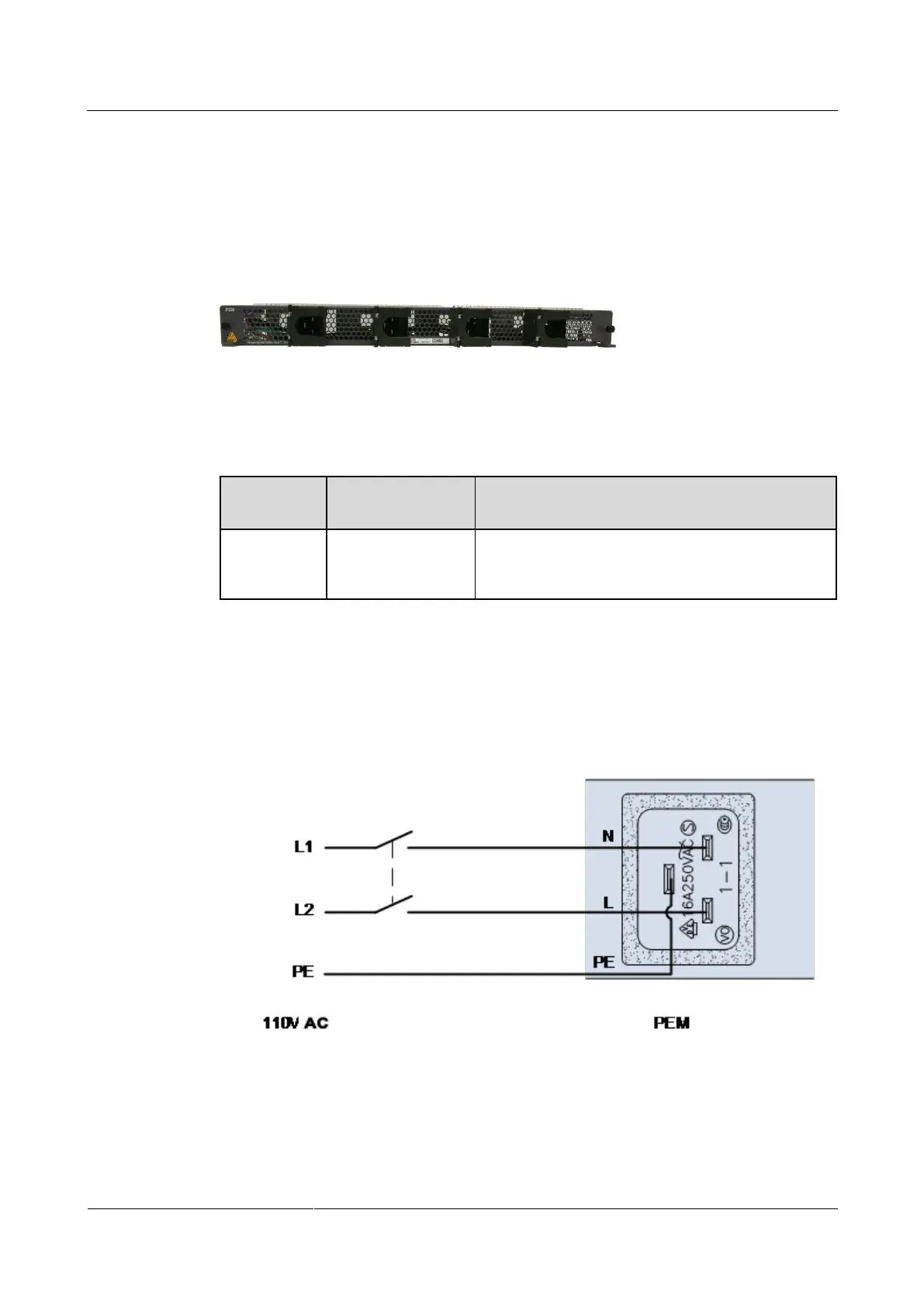
Input upstream requirements
Supports 220 V AC input. In 110 V AC scenario, the dual-live wire input mode can be
used, as Figure 1-70 shown in.
Figure 1-70 110 V dual-live-wire connection
Users are required to provide protective components for the upstream PDF or the power
cabinet. The rated current of each channel is not less than the AC 16 A.
 Loading...