MAINTENANCE
HySpeed HT2000 Instruction Manual 8-27
20
Check Pump, Motor and Solenoid Valve (V1)
1. If coolant is not flowing, check to see if motor and valve V1 are getting 240VAC. Note: The 240VAC relay
(CR3) on PCB1 will not close until the first five (5) interlocks (STATUS) indicators are satisfied. (See
Startup Sequence flowchart)
2. If motor, pump and valve all seem to be functioning and the flow is not sufficient, replace the pump and
motor assembly.
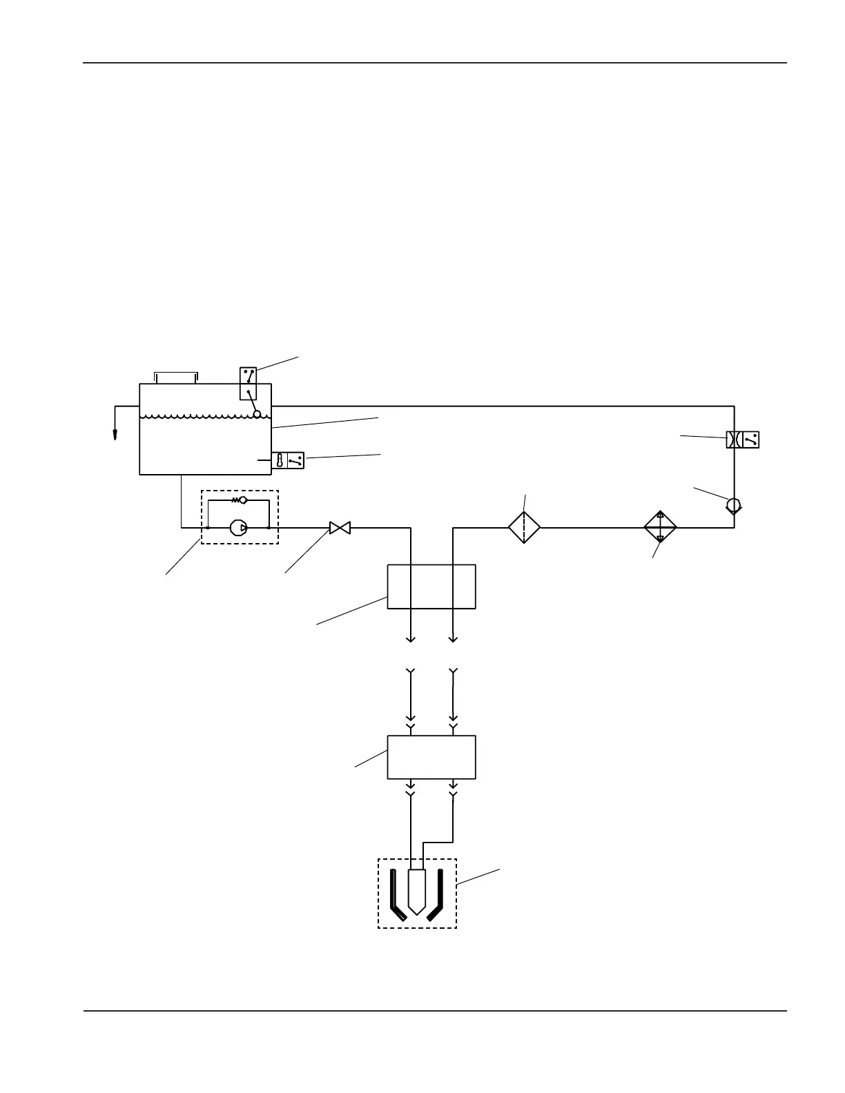
Figure 8-7 Plumbing Schematic of Power Supply Reservoir Assembly
with RHF Console and Torch
Cathode Block
(in back of
power supply)
Remote High Frequency
Console
Heat
Exchanger
Check
Valve
Flow Switch
FS1
Solenoid Valve
V1
Particulate
Filter
Coolant Reservoir
Float Switch
LS1
Temperature Switch
TS1
Torch
Pump with
Relief Valve
 Loading...


