INSTALLATION
4-20 HySpeed HT2000 Instruction Manual
19
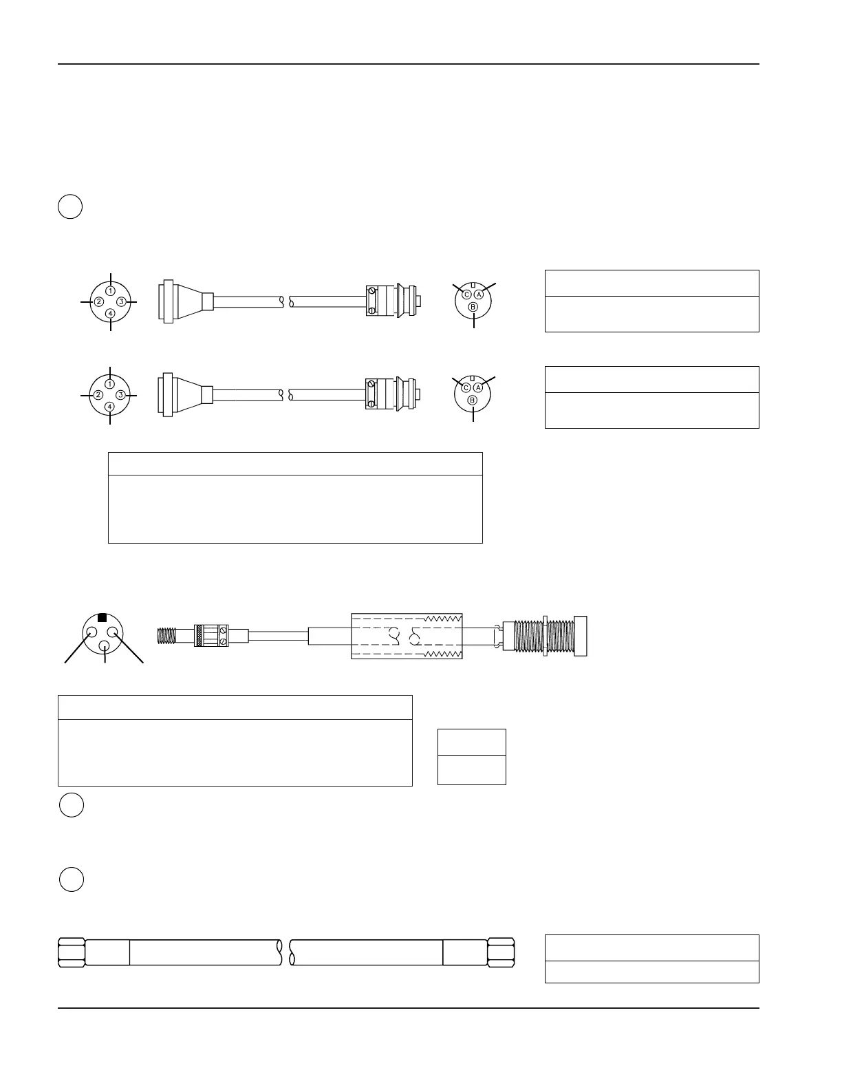
Initial Height Sensing (IHS) Connections
Note: If using Command THC, refer to manual #802780.
See page 4-18 for IHS connection to power supply.
IHS Sensor cables/Inductor Probes – IHS to Inductor Probes
The two sensor cables are components of the IHS leads packages – see page 9-43.
Function IHS End Color Probe End
Power (+15 VDC) 4 Red A
Common 2 Black B
Signal 1 Clear C
Shield 3 Braid
The two inductive probes come as part of the IHS torch mounting subassembly – see page 9-43.
IHS Air Supply – Air Supply to IHS Module
The customer must supply the 20 psig regulated shop air and the air hose.
Air Hose Assembly – IHS Module to Inductive Sensor Air Cylinder
The 40-foot air hose is a component of the IHS leads packages – see page 9-43.
Function Pin Color
Power (+15 VDC) A Brown
Common B Blue
Signal C Black
14
1
4
23
C
A
B
Rear View
15
16
Part No. Length
023888 2 ft (.6 m)
023869 40 ft (12 m)
Part No. Length
023889 2 ft (.6 m)
023870 40 ft (12 m)
C
BA
Part No.
005074
Part No. Length
024144 40 ft (12 m)
1
4
23
C
A
B
8X2
8X4
8X3
8X5