MAINTENANCE
1
powermax1000 Service Manual 3-9
Hypertherm IGBT tester
Use the Hypertherm IGBT tester (part number 128883) as described in the following sections or assemble your
own IGBT tester from the schematic diagram shown in
IGBT tester schematic
and use it to test the IGBTs.
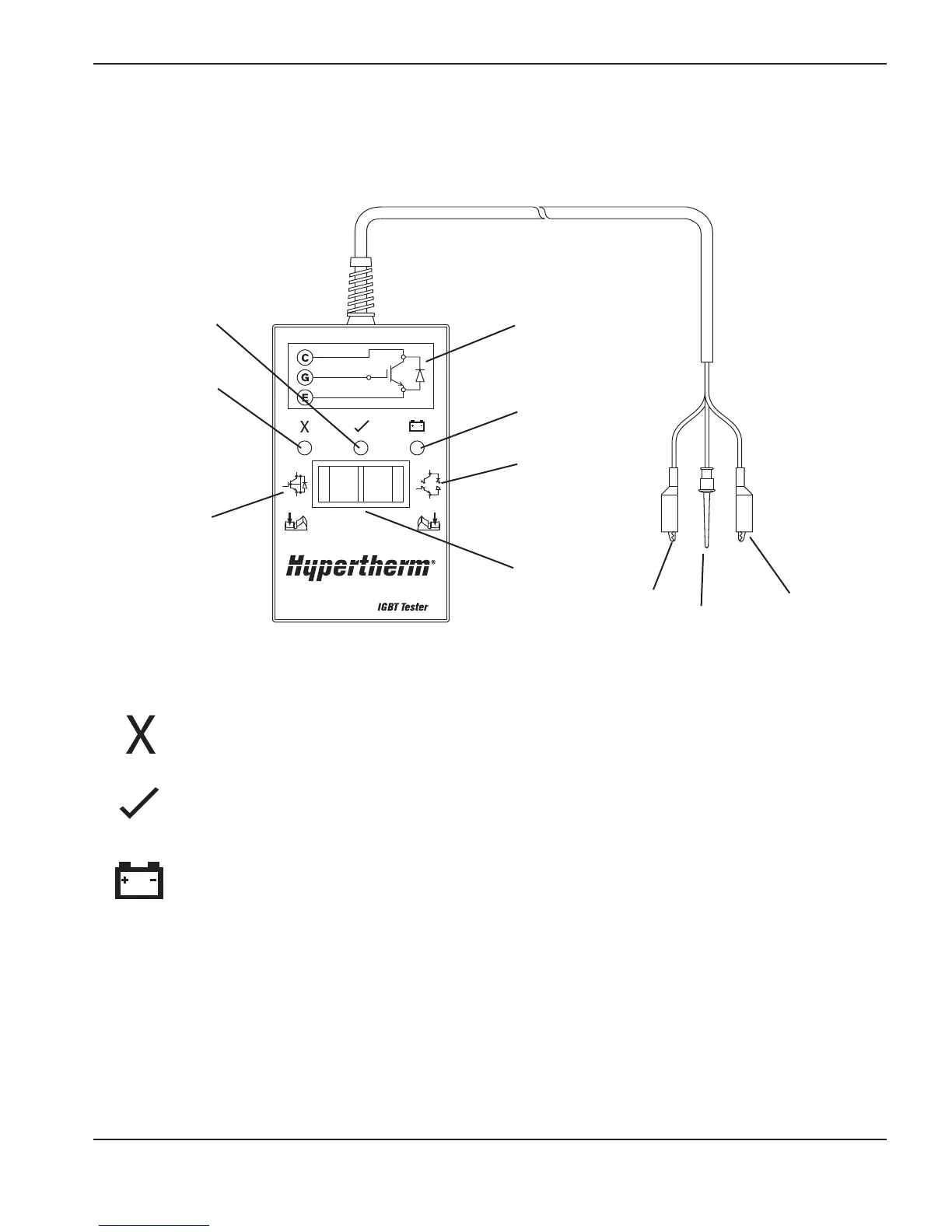
Red “fail” LED
When illuminated, this LED indicates that the IGBT failed the test for an open IGBT when the switch
is pressed to the right or for a shorted IGBT when the switch is pressed to the left.
Green “pass” LED
When illuminated, this LED indicates that the IGBT passed the test for an open IGBT when the
switch is pressed to the right or for a
shorted IGBT when the switch is pressed to the left.
Red “low battery” LED
When illuminated, this LED indicates that the remaining voltage in the battery is insuf
ficient to power
the test circuitry. Replace the battery.
Note:
The Hypertherm IGBT tester requires a minimum of 8V to properly power its circuitry.
Indicator LEDs and device tests
Pass LED
(green)
Collector
(red)
Circuit
diagram
Fail LED
(red)
Test for
shorted IGBT
Low battery
LED (red)
Test for
open IGBT
Rocker
switch
Gate
(yellow)
Emitter
(black)
IGBT test preparation
Before testing with the Hypertherm IGBT
tester
, c
onnect the colored leads to the IGBT
as shown below
.
Before an IGBT
can be tested, it must be electrically isolated from all circuits. If the IGBT
is installed in a power
supply, remove the power board and any lead connections before testing.

 Loading...


