MAINTENANCE
3-12 powermax1000 Service Manual
1
IGBT device test using non-Hypertherm tester
The device tester shown in
Schematic for building an IGBT tester
has one LED and one pushbutton switch that are
used in combination to perform two tests.
1. Visually inspect the IGBT for cracks or black marks. If damaged, replace the IGBT.
2. Verify that the 9V battery reads greater than (>) 8.0V.
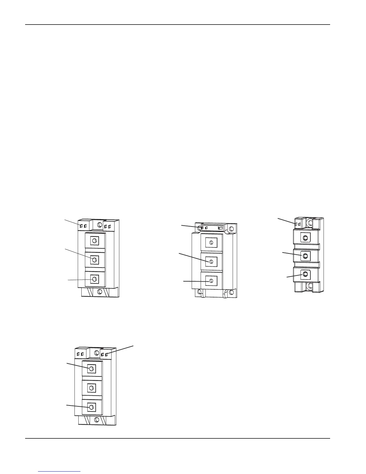
3. Connect the test leads as shown below.
Note: The IGBT must be electrically isolated before the test is performed.
4. With the test leads connected and without pressing the pushbutton switch, the LED should not illuminate. If the
LED is illuminated, then the IGBT is shorted. Replace the IGBT.
5. With the test leads connected, press the push button switch. This time, the LED should illuminate. If the LED
does not illuminate, then the IGBT is open. Replace the IGBT.
Yellow lead
Gate 1 (G1)
Black lead
Emitter 1 (E1)
Red lead
Collector 1 (C1)
IGBT, Inverter
Test 1
Yellow lead
Gate (G)
Black lead
Emitter (E)
Red lead
Collector (C)
IGBT, PFC
Yellow lead
Gate (G)
Red lead
Collector (C)
Black lead
Emitter (E)
IGBT, Pilot arc
IGBT, Inverter,
Test 2
Red lead
Collector 2 (C2)
Black lead
Emitter 2 (E2)
Yellow lead
Gate 2 (G2)

 Loading...


