EasyManuals Logo
Home>Hypertherm>Welding System>powermax1000

Hypertherm powermax1000 Service Manual

Hypertherm powermax1000
92 pages
To Next Page IconTo Next Page
To Previous Page IconTo Previous Page
Page #56 background imageLoading...
Page #56 background image
MAINTENANCE
1
powermax1000 Service Manual 3-23
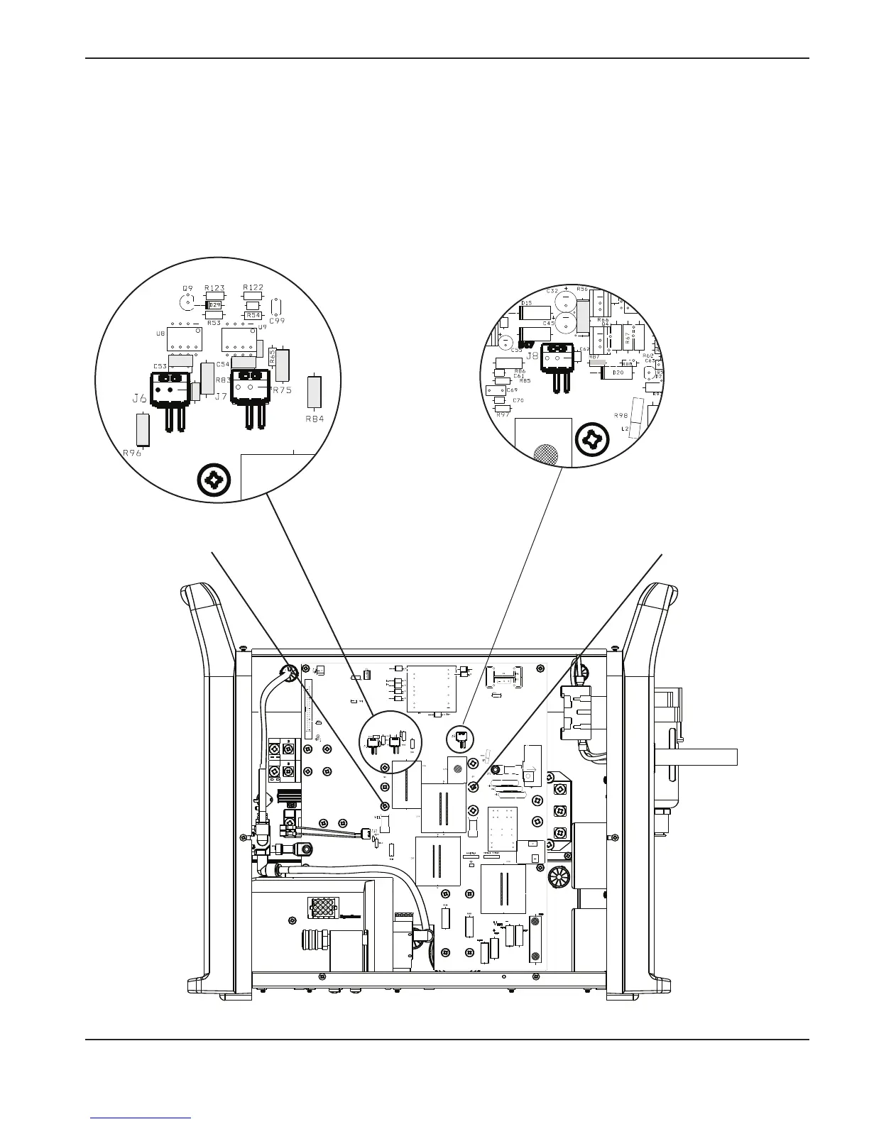
Test 5 – inverter IGBT (Q6) and PFC IGBT (Q7)
Check the resistance of the gate-drive circuit.
If the values are not ±25% of the values shown below, replace the power board (PCB2) and the appropriate
IGBT.
If the values are correct, check both IGBTs with an IGBT tester. If one IGBT fails, replace the power board
(PCB2) and the failed IGBT.
80
C100
Inverter IGBT (Q6)
PFC IGBT (Q7)
o o
o o
R65
R82
Inverter
R82 = 994
R83 = 6.1
R65 = 995
R75 = 6.1
R84 = 10.4
R96 = .4
80
C100
PFC
R87 = 994
R56 = 4.1
R98 = 1

Table of Contents

Other manuals for Hypertherm powermax1000

Questions and Answers:

Question and Answer IconNeed help?

Do you have a question about the Hypertherm powermax1000 and is the answer not in the manual?

Hypertherm powermax1000 Specifications

General IconGeneral
BrandHypertherm
Modelpowermax1000
CategoryWelding System
LanguageEnglish

Related product manuals