MAINTENANCE
1
powermax1000 Service Manual 3-19
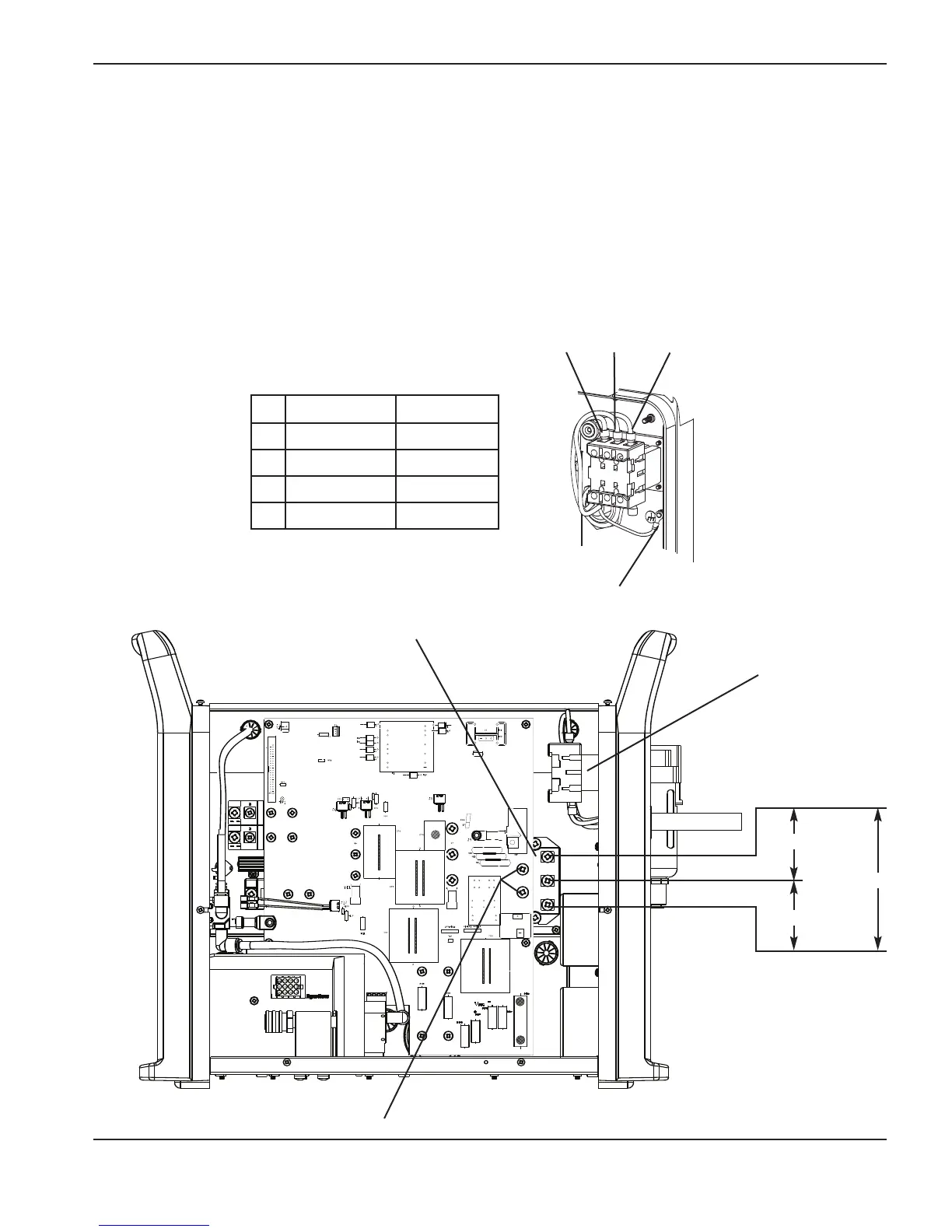
Test 1 – voltage input
• Check the line voltage to the top of the power switch (S1).
• Check the input voltage to the input diode bridge.
• The AC voltage between any 2 input wires should equal the line voltage.
• If there is proper voltage to the power switch and low voltage to the input diode, replace the power switch.
• For CE systems, check the voltage at the CE filter. If there is proper voltage to the CE filter and low
voltage to the input diode, replace the CE filter.
• Check the output voltage of the input diode bridge.
• Output VDC = Line Voltage x 1.414 VDC.
Note: All values can be ±15%.
= Line voltage*
= Line voltage
= Line voltage*
Input diode bridge
Power switch (S1)
* Single phase
Line voltage x 1.414
Ground (PE)
L1 (U)
L2 (V)
L3 (W)
Standard unit CE unit
L1 Black Black (U)
L2 White Blue (V)
L3 Red Brown (W)
PE Green Green/Yellow

 Loading...


