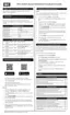
Fan Speed Operation
Voltage
Terminal
Description and Defaults Range (CFM)
W1 Heating stage 1 = 600 CFM 180-1000 (for mode 1 Stage Heat
max = 1200)
W2 Heating stage 2 = 960 CFM 180-1200 (must be ≥ 1 Stage Heat)
Y1 Cooling stage 1 = 840 CFM 180-1000 (for mode 1 Stage AC/HP
max = 1200)
Y2 Cooling stage 2 = 1200 CFM 180-1200 (must be ≥ AC/HP Stage 1)
G Fan on speed = 275 CFM 180-1200
AHU1600
W1 Heating stage 1 = 800 CFM 240-1280 (for mode 1 Stage Heat
max = 1600)
W2 Heating stage 2 = 1280 CFM 240-1600 (must be ≥ 1 Stage Heat)
Y1 Cooling stage 1 = 1120 CFM 240-1280 (for mode 1 Stage AC/HP
max = 1600)
Y2 Cooling stage 2 = 1600 CFM 240-1600 (must be ≥ AC/HP Stage 1)
G Fan on speed = 320 CFM 240-1600
AHU2000 LV
W1 Heating stage 1 = 1000 CFM 240-1600 (for mode 1 Stage Heat
max = 2000)
W2 Heating stage 2 = 1600 CFM 240-2000 (must be ≥ 1 Stage Heat)
Y1 Cooling stage 1 = 1400 CFM 240-1600 (for mode 1 Stage AC/HP
max = 2000)
Y2 Cooling stage 2 = 2000 CFM 240-2000 (must be ≥ AC/HP Stage 1)
G Fan on speed = 400 CFM 240-2000 (must be ≥ AC/HP Stage 1)
 Loading...