System-board layouts
The following illustrations show the connectors, LEDs, and jumpers on the memory
card, microprocessor board, PCI board, SAS backplane, and I/O board. The
illustrations in this document might differ slightly from your hardware.
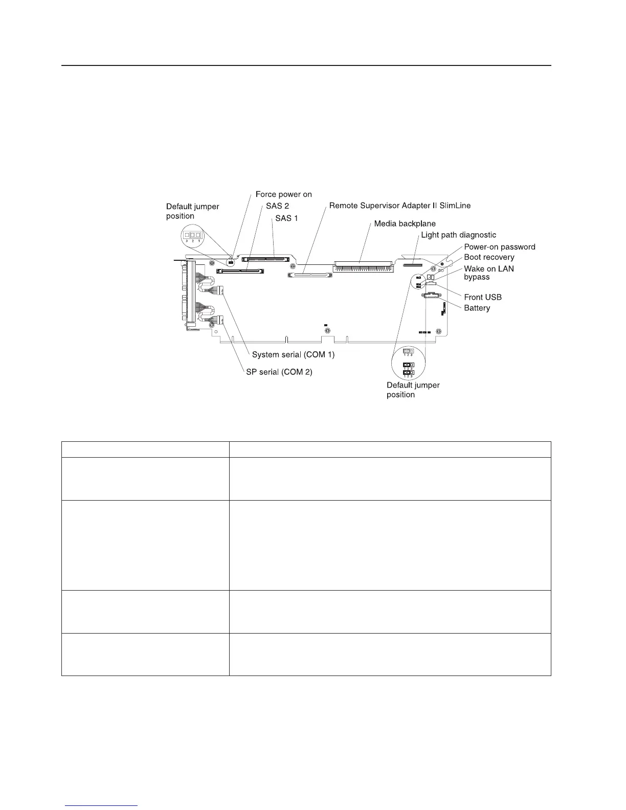
I/O board internal connectors and jumpers
The following illustration shows the internal connectors and jumpers on the I/O
board.
Table 2 describes the function of each three-pin jumper block.
Table 2. I/O board jumper blocks
Jumper name Description
Force power on (J2) The default position is pins 1 and 2. Change the position of this
jumper to pins 2 and 3 to force the server to startup when you
connect the server to ac power.
Power-on password (J9) The default position is pins 1 and 2. Change the position of this
jumper to pins 2 and 3 to bypass the power-on password check.
Changing the position of this jumper does not affect the
administrator password check if an administrator password is set. If
the administrator password is lost, the operator information panel
must be replaced.
Boot recovery (J14) The default position is pins 1 and 2 (use the primary page during
startup). Move the jumper to pins 2 and 3 to use the secondary
page during startup.
Wake on LAN
®
bypass (J15) The default position is pins 1 and 2. Move the jumper to pins 2 and
3 to prevent a Wake on LAN packet from waking the system when
the system is in the powered-off state.
8 IBM System x3850 Type 8864: Problem Determination and Service Guide
 Loading...


