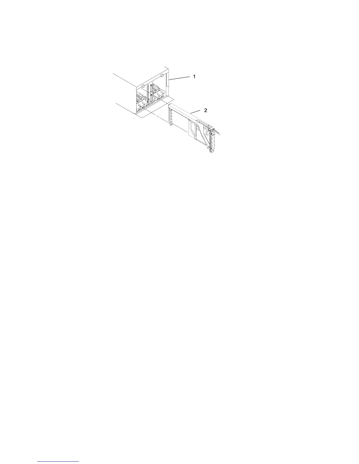
c. Hold the assembly straight on and level with the slot.
d. Align the bottom edge of the PCI cassette cover with the PCI adapter guide rail
on the I/O backplane.
Note: If there is a cassette to the left of the one that you are installing, align
the ridge on the cover with the tick in the notch of the neighboring
cassette.
e. Slide the cassette partially into the guide.
f. Ensure that the dovetail on the top track aligns with its mating component(s) on
both sides.
g. When the cassette is fully inserted, prepare to activate the handle, lower the
gray locking bar. Lift the handle up completely until you hear a click. The PCI
adapter should be completely seated.
Note: To enable proper insertion of the adapter, some minor forward or
backward movement of the PCI adapter cassette might be necessary.
h. Set the color slide to the orange color indicating that the adapter in the
cassette is hot-pluggable.
22. Connect appropriate cables and devices to the adapter.
23. Continue to follow the screen instructions until you receive a message that the
replacement is successful. Successful replacement is indicated by the OK message
displayed next to the Command field at the top of the screen.
24. Press the F3 key to return to the PCI Hot-Plug Manager menu.
25. Select Install/Configure Devices Added After IPL and press Enter. Then follow
the instructions on the screen. Successful replacement is indicated by the OK
message displayed next to the Command field at the top of the screen.
26. If you do not have other adapters to replace, continue with the next step.
OR
If you have other adapters to replace, press the F3 key to return to the PCI
Hot-Plug Manager menu and then return to step 13 on page 64.
27. Press F10 to exit the Hot-Plug Manager.
If you have added, removed, or replaced any adapters, run the diag -a command.
If the system responds with a menu or prompt, follow the instructions to complete
the device configuration.
Chapter 8. Removal and Replacement Procedures 65
 Loading...