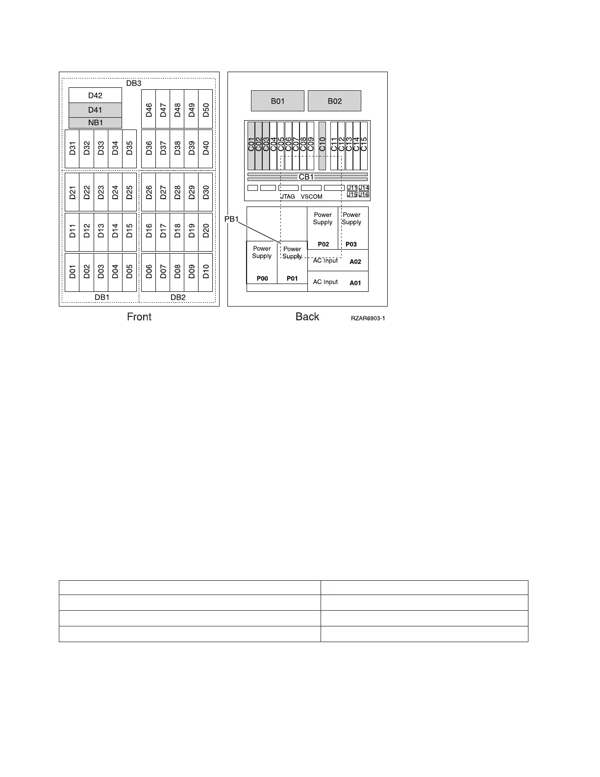
Notes:
1. The FC 9094 I/O Tower contains three system PCI busses.
2. In FC 9094 I/O Tower, the bus numbers assigned to the busses are not required to be in any order.
3. Card position C01 is required to be an I/O processor.
4. Card positions C05 and C11 are required to be either I/O processors or Integrated xSeries
(TM)
Servers
(IXS).
5. J11 is an RPO connection, J14 is an uninterruptable power supply connector, J15 is an SPCN 1
connector, and J16 is an SPCN 2 connector.
6. Multi-adapter bridge domains are labeled PCI Bridge Set inside the tower.
7.
The following table provides information necessary to identify the IOP to which IOAs are assigned.
v The left column indicates the domain in which IOA assignment is allowed.
v The right column is used to determine the IOP to which an IOA is assigned.
v The first position in the list must be an IOP. The remaining positions may be IOPs or IOAs. IOAs are
assigned to the first IOP located to their left in the list. Although IOAs can be manually reassigned
using SST/DST, the IOA assignments return to the default order after each IPL.
Table 2. IOA assignment rules
Multi-adapter bridge domain / PCI bridge set IOA assignment rules
C01 - C04 C01, C02, C03, C04
C05 - C09 C05, C06, C07, C08, C09
C11 - C15 C11, C12, C13, C14, C15
Table 3. FRU locations and failing components for FC 9094 Base I/O Tower
The following table gives the components available for callout on the FC 9094 Base I/O Tower. It matches
those components with the FRU containing the the component. The other columns give location
information, CCIN information, a link to a remove and replace procedure, and additional comments.
292 Hardware (Remove and Replace; Part Locations and Listings)
 Loading...


