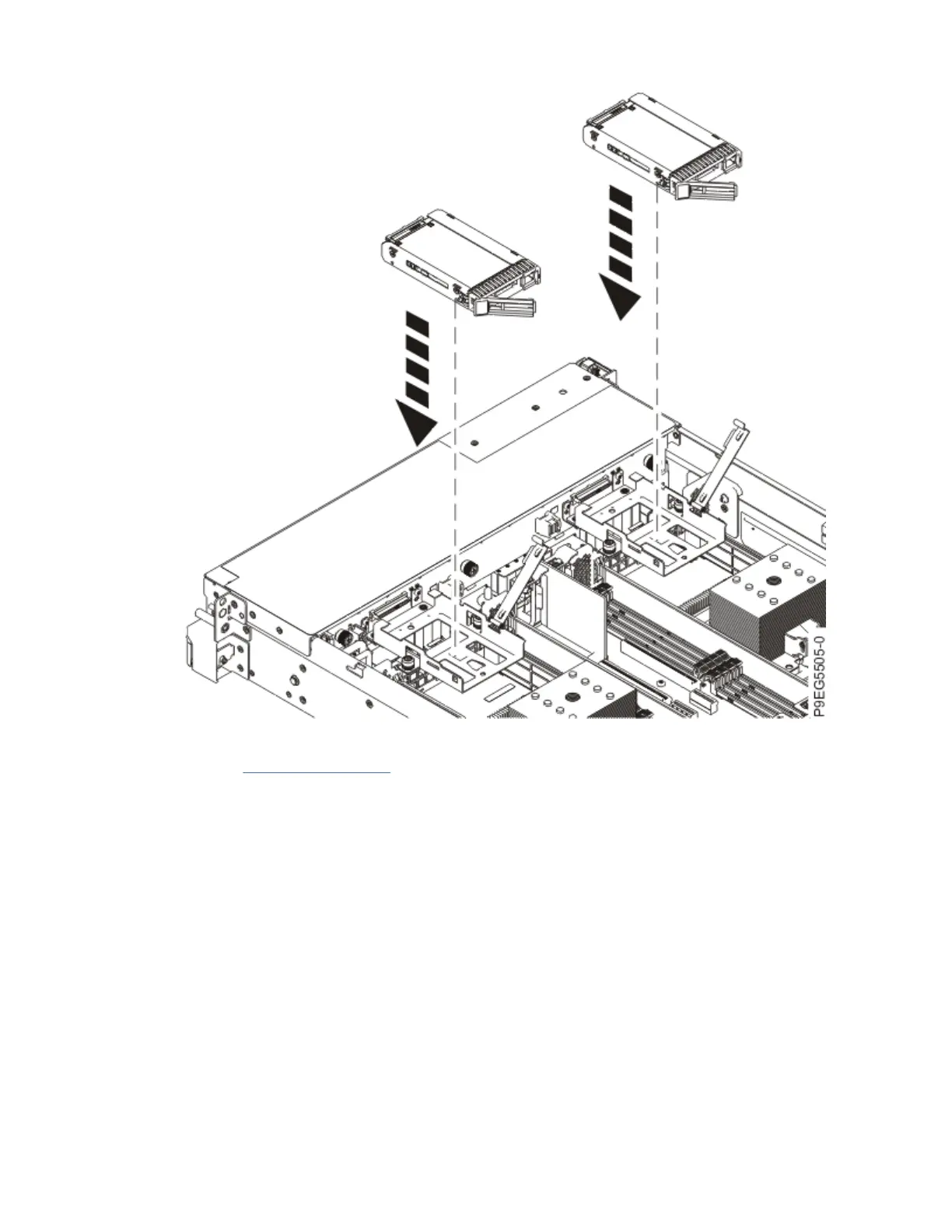
Figure 36. Lowering the BPM into the drive tray
c) Refer to Figure 37 on page 38. Rotate the BPM on its longer axis to expose the cable connectors
at the bottom of the BPM.
d) Using your cable labels, connect both BPM cables to the BPM as shown in the following image.
The cables are routed through the cutout in the BPM. Push the BPM cables in until the connector
latches click.
Drive backplanes for the 5105-22E, 9008-22L, 9009-22A, 9009-22G, or 9223-22H
37
 Loading...