Identify the hardware components: 2077-92F, 2077-A9F
You should become familiar with the external components of the 2077-92F, 2077-A9F expansion
enclosure.
Components on the front of the enclosure
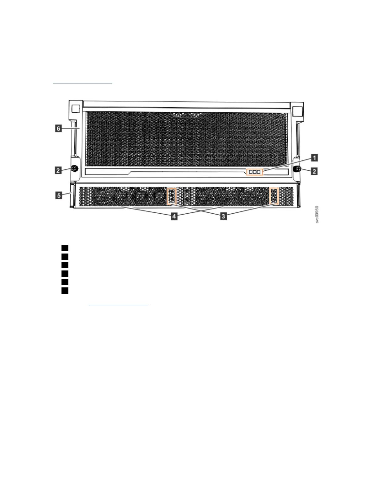
Figure 20 on page 32 shows the front of the 2077-92F, 2077-A9F expansion enclosure. In the gure, all
parts are installed in the enclosure.
Figure 20. Features on the front of the 2077-92F, 2077-A9F expansion enclosure
1 Display panel indicators
2 Rack retention thumb screws
3 Power supply unit indicators
4 Power supply units (PSUs)
5 PSU fascia (1U)
6 Front fascia (4U)
However, as Figure 21 on page 33 shows, the 4U and 1U fascias are packaged separately. You must
attach them to the front of the 2077-92F, 2077-A9F expansion enclosure as part of the initial installation
process.
32
Storwize V5100 : Quick Installation Guide for MTM 2078-424, 2078-12F, 2078-24F, 2078-92F, and 2078-
U5B
 Loading...