LEDs inside of the expansion enclosure
Each of the drives and secondary expansion modules within the 2077-92F, 2077-A9F expansion
enclosure has two LED indicators. To view the drives and secondary expansion modules, you must
remove the cover of the enclosure, as described in “Removing the top cover: 2077-92F, 2077-A9F ” on
page 38.
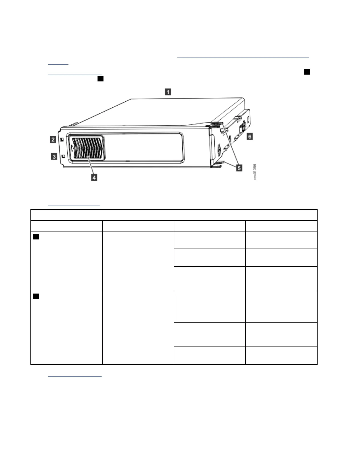
Figure 67 on page 65 shows the components of a drive assembly. Each drive has an online indicator ( 2 )
and fault indicator ( 3 ).
Figure 67. LEDs on a drive assembly
Table 14 on page 65 describes the meaning of the LEDs on each drive.
Table 14. LED indicators on drives
Function Color Status Description
2 Activity Green On The drive is ready to be
used.
Flashing The drive is operating and
I/O is occurring.
Off The drive is not installed
or an installed drive is not
ready to be used.
3 Fault Amber On A fault occurred on the
drive. The LED is turned
off when the drive is
removed and replaced.
Flash The drive is being
identied, a fault might or
might not be detected.
Off The installed drive is
operating normally.
Figure 68 on page 66 shows the LEDs on a secondary expansion module.
Chapter 2. Installing the system hardware
65
 Loading...