About this task
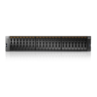
The 2077-92F, 2077-A9F expansion enclosure has two power supply units (PSUs) that are accessible
from the front of the enclosure ( 4 in Figure 61 on page 60). As the gure also shows, the PSUs are
covered by the 1U fascia ( 5 ).
Figure 61. Features on the front of the 2077-92F, 2077-A9F expansion enclosure
1 Display panel LEDs
2 Rack retention thumb screws
3 Power supply unit LEDs
4 Power supply units (PSUs)
5 PSU fascia (1U)
6 Front fascia (4U)
Each PSU has a power supply connector and power cable, which are accessible from the back of the
enclosure. Power is provided by plugging a C19-C20 power cable into each power supply unit and, if
necessary, turning on the power source. The expansion enclosure does not have a power button.
Procedure
1. Connect the C19-C20 power cables to the power connectors on the rear of the expansion enclosure.
The enclosure automatically powers on and begins its Power On Self-Tests (POST).
2. Secure the power cables in the cable retainer at each power connector on the rear of the enclosure, as
shown in Figure 62 on page 61. Also, ensure that each cable is installed along one of the cable
management arms. The cable management arms also support the SAS cables.
60
Storwize V5100 : Quick Installation Guide for MTM 2078-424, 2078-12F, 2078-24F, 2078-92F, and 2078-
U5B
 Loading...