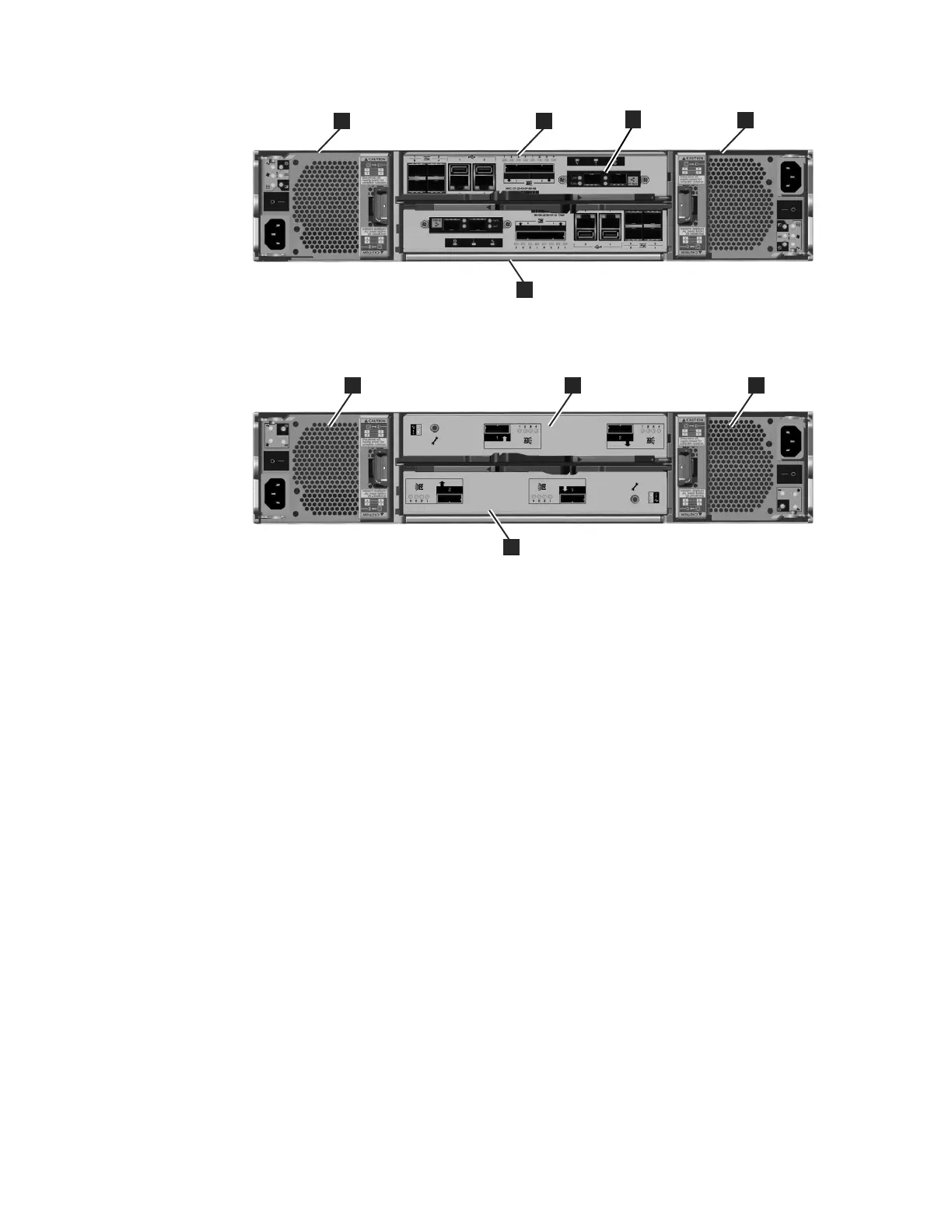
1 Power supply unit 1
2 Power supply unit 2
3 Canister 1
4 Canister 2
Power supply unit and battery for the control enclosure
The control enclosure contains two power supply units, each with an integrated
battery.
The two power supply units in the enclosure are installed with one unit top side
up and the other inverted. The power supply unit for the control enclosure has six
LEDs.
There is a power switch on each of the power supply units. The switch must be on
for the power supply unit to be operational. If the power switches are turned off,
or the main power is removed, the integrated batteries temporarily continue to
supply power to the node canisters. As a result, the canisters can store
configuration data and cached data to their internal drives. Battery power is
required only if both power supply units stop operating.
Figure 10 on page 7 shows the location of the LEDs 1 in the rear of the power
supply unit.
1
3
2
4
svc00726
5
Figure 8. Rear view of a model 2076-312 or a model 2076-324 control enclosure
1
2
3
svc00610
4
Figure 9. Rear view of a model 2076-212 or a model 2076-224 expansion enclosure
6 Storwize V7000: Troubleshooting, Recovery, and Maintenance Guide
 Loading...