There is a power switch on each of the power supply units. The switch must be on
for the power supply unit to be operational. If the power switches are turned off,
the power supply units stop providing power to the system.
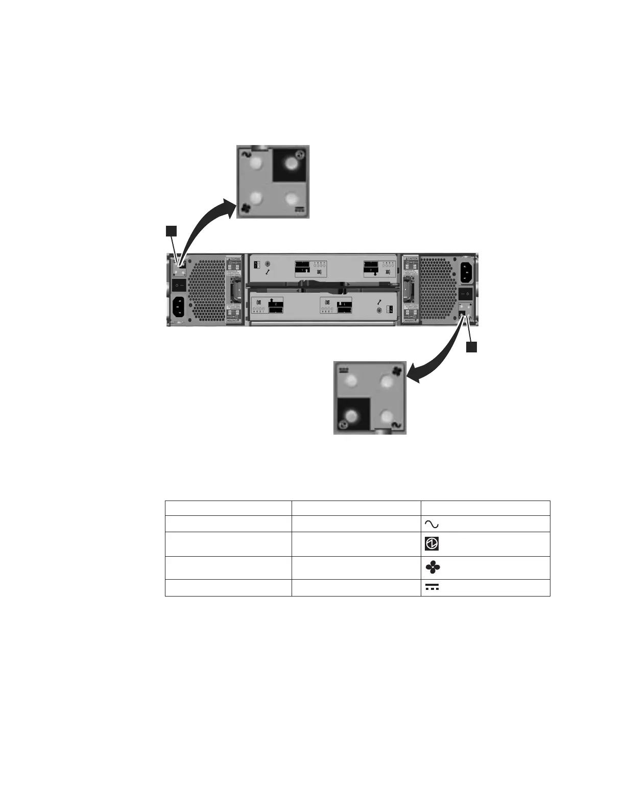
Figure 11 shows the locations of the LEDs 1 in the rear of the power supply unit.
Table 8 identifies the LEDs in the rear of the expansion enclosure.
Table 8. Power supply unit LEDs in the rear of the expansion enclosure
Name Color Symbol
ac power failure Amber
Power supply OK Green
Fan failure Amber
dc power failure Amber
See “Procedure: Understanding the system status using the LEDs” on page 54 for
help in diagnosing a particular failure.
Node canister ports and indicators
The node canister has indicators and ports but no controls.
Fibre Channel ports and indicators
The Fibre Channel port LEDs show the speed of the Fibre Channel ports and
activity level.
1
svc00671
1
Figure 11. LEDs on the power supply units of the expansion enclosure
8 Storwize V7000: Troubleshooting, Recovery, and Maintenance Guide
 Loading...