5. Rotate the back of the heat sink out of the retention bracket and remove the
heat sink from the server.
6. Lift the microprocessor-release lever to the fully open position (approximately
135° angle) and remove the microprocessor from the server.
To install a microprocessor, complete the following steps:
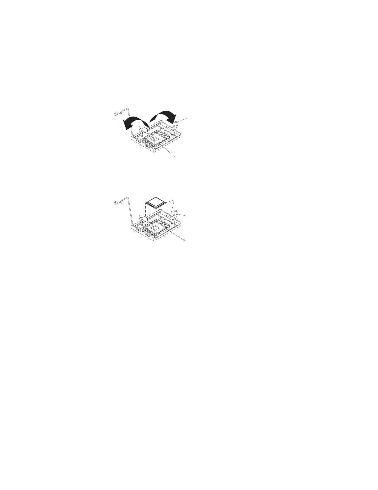
1. Release the microprocessor retention latch by pressing down on the end,
moving it to the side, and slowly releasing it to the open (up) position.
Microprocessor
release lever
(fully open)
Microprocessor
bracket frame
2. Position the microprocessor over the microprocessor socket as shown in the
following illustration. Carefully press the microprocessor into the socket.
Microprocessor
Microprocessor socket
Microprocessor
release lever
Alignment marks
3. Close the microprocessor-release lever to secure the microprocessor.
4. Open the heat-sink release lever and install a heat sink on the microprocessor;
then, close the release lever.
5. If you are installing a new heat sink, remove the cover from the bottom of the
heat sink. If you are reinstalling a heat sink that was previously removed, go to
“Thermal grease” on page 93 for instructions for replacing the contaminated or
missing thermal grease; then, return to this procedure and continue with step
6.
6. If necessary, remove the cover from the bottom of the heat sink.
7. Place the tab on the heat sink into the slot in the retention bracket; then, rotate
the heat sink into place and close the heat-sink release lever.
Note: If you are installing an additional microprocessor in microprocessor
socket 2, you must also install a VRM.
8. If necessary, install a VRM in the connector:
a. Open the retaining clips on each end of the VRM connector.
b. Turn the VRM so that the keys align with the slot.
c. Insert the VRM into the connector by aligning the edges of the VRM with
the slots at the end of the VRM connector. Firmly press the VRM straight
down into the connector by applying pressure on both ends of the VRM
simultaneously. The retaining clips snap into the locked position when the
VRM is seated in the connector.
9. Lower the power-supply cage and install the power supply or power supplies. If
necessary, reinstall the air baffle on the fan cage.
10. Reinstall the left-side cover.
92 IBM System x3500 Type 7977: Problem Determination and Service Guide
 Loading...