8. Perform any configuration tasks that are required for the adapter.
9. Reinstall the cover (see “Replacing the cover” on page 209).
10. Slide the server into the rack.
11. Reconnect the power cords and any cables that you removed.
12. Turn on the peripheral devices and the server.
Removing a ServeRAID SAS/SATA controller
Use this information to remove a ServeRAID SAS/SATA controller.
About this task
The ServeRAID SAS/SATA controller can be installed in the dedicated connector
on the system board or PCI riser-card slots (see “System-board internal connectors”
on page 28 for the location of the connectors).
You can replace the ServeRAID controller with another supported ServeRAID
controller. For a list of supported ServeRAID controllers, see http://
www.ibm.com/systems/info/x86servers/serverproven/compat/us/.
Note: For brevity, in this documentation the ServeRAID SAS/SATA controller is
often referred to as the SAS/SATA adapter or the ServeRAID adapter.
To remove the SAS/SATA adapter from the system board, complete the following
steps:
Procedure
1. Read the safety information that begins on “Safety” on page vii and
“Installation guidelines” on page 33.
2. Turn off the server and peripheral devices and disconnect all power cords.
3. Remove the cover (see “Removing the cover” on page 36).
4. Remove PCI riser-card assembly 1 if necessary (see “Removing a PCI riser-card
assembly” on page 244).
5. Locate the SAS/SATA adapter between PCI slot 1 and microprocessor 1.
6. Disconnect the signal cables and power cables from the connectors on the
SAS/SATA adapter and note their locations.
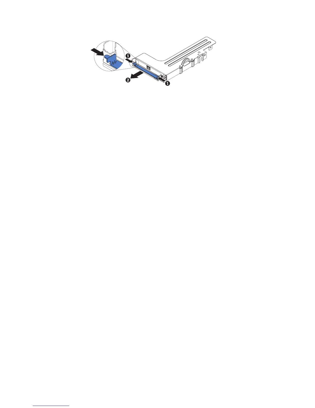
7. Grasp the end of the SAS/SATA adapter near microprocessor 1 while you slide
the brackets. Slide the retention bracket (near the chassis) toward the chassis;
then, slide the other retention bracket toward the power supplies.
Figure 149. Latch removal
Chapter 6. Removing and replacing components 253
 Loading...