3 - 1
SECTION 3
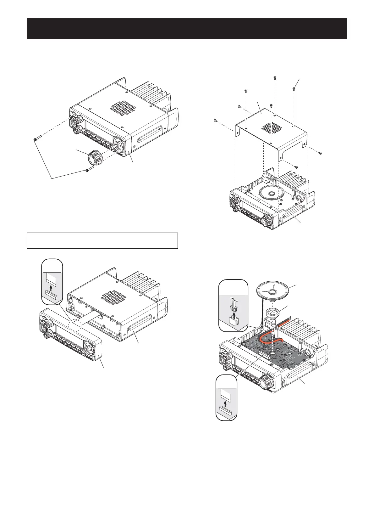
DISASSEMBLY INSTRUCTION
BE CAREFUL about the fl at cable and connector when
separating the front panel from the chassis.
REMOVING THE FRONT PANEL
1) Remove [DIAL] from the front panel.
2) Remove 2 hex screws from the front panel.
REMOVING THE MAIN UNIT
1) Remove 8 screws from the top cover, and then re-
move the top cover from the chassis.
W2
MAIN UNIT
MAIN UNIT
MAIN UNIT
Hex screws
[DIAL]
Front panel
W2
MAIN UNIT
MAIN UNIT
MAIN UNIT
Screws
Top cover
Chassis
FLAT
CABLE
MAIN UNIT
MAIN UNIT
MAIN UNIT
Front panel
Chassis
3) CAREFULLY separate the front panel from the
chassis.
4) Disconnect the fl at cable from the LOGIC UNIT.
2) Disconnect the fl at cable from the MAIN UNIT.
3) Disconnect the speaker cable from the MAIN UNIT.
4) Remove the speaker and speaker cap from the
MAIN UNIT.
(Continued on page 3-2.)
SPEAKER
CABLE
FLAT
CABLE
MAIN UNIT
MAIN UNIT
MAIN UNIT
Speaker
Speaker cap
Chassis
 Loading...