4 - 1
• RF CIRCUITS
• 1ST IF CIRCUITS
SECTION 4
CIRCUIT DESCRIPTION
ANTENNA
LPF
BPF BPF
ANT
SW
RF
AMP
ATT
LIMIT
D24-D25
D29-D32
D28
TX circuits
D26
D23
D22,D34
<- 1st IF circuits
MAIN UNIT
Q32
LPF
IF
AMP BPF
XTAL
FI3
RF circuits <-<- 2nd IF circuits
Q27
D17
MAIN UNIT
Q28
LIMIT
46.35MHz
Rx;136.000-174.000MHz
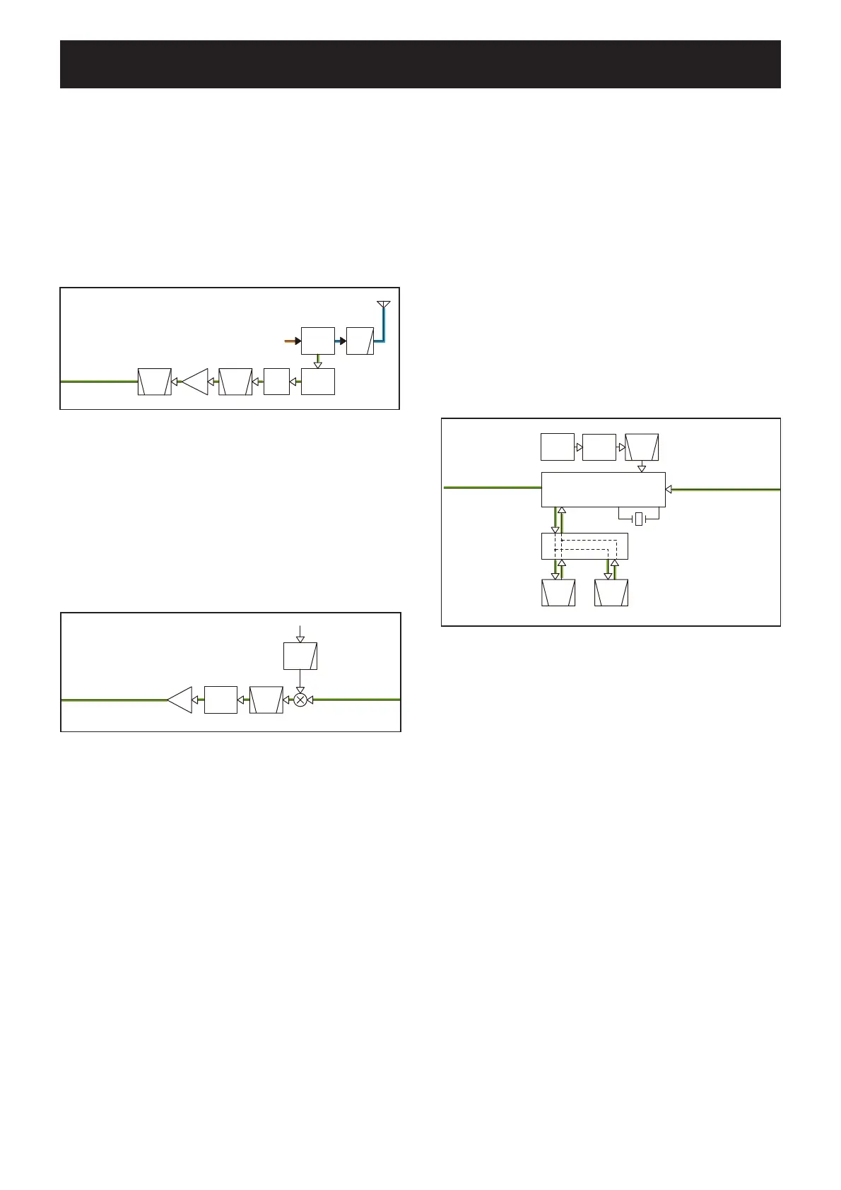
4-1 RF CIRCUITS
The RX signal from the antenna is passed through the LPF
(L36, L39, L41, L42, C291, C295, C296, C298, C300, C303,
C304, C306, C307), antenna SW (D29–D32) and tuned BPF
(D23, L34, C279), and then applied to the RF AMP (Q32).
The amplifi ed RX signal is passed through a two-staged
tuned BPF (D22, D34, L27, L28, C213, C224, C227, C236,
C238, C242, C249), and then applied to the 1st IF circuits.
1ST IF CIRCUITS
The RX signal from the RF circuits is applied to the 1st mixer
(Q28), to be mixed with the 1st LO signal from the RX VCO
(Q14, D10–D11, L6), resulting in the 46.35 MHz 1st IF sig-
nal. The 1st IF signal is passed through the 1st IF fi lter (FI3)
to remove unwanted signals, and then applied to the 1st IF
AMP (Q27). The amplifi ed 1st IF signal is applied to the 2nd
IF circuits.
2ND IF CIRCUITS
The 1st IF signal from the 1st IF circuits is applied to the IF
IC (IC3).
The IF IC contains the 2nd mixer, 2nd IF AMP, detector, and
so on, in its package.
The 1st IF signal is mixed with the 2nd LO signal at the in-
ternal 2nd mixer, resulting in the 455 kHz 2nd IF signal. The
2nd IF signal is passed through the 2nd IF fi lter (FI1: for wide
mode, FI2: for narrow mode) to remove sideband noise, and
then applied to the internal 2nd IF AMP. The amplifi ed 2nd IF
signal is applied to the quadrature detector circuit for frequen-
cy-demodulation.
The demodulated AF signal is output from the IF IC (pin 9),
and then applied to the RX AF circuits on the LOGIC UNIT.
• 2ND IF CIRCUITS
BPF
CERAMIC
BPF
CERAMIC
X2
X3 BPF
2nd IF circuits <-
REF
OSC
X1
IF IC
FI1
FI2
W/N
SW
Q4,D1-D2,D5-D6
MAIN UNIT
DETO
<- RX AF circuits
IC3
Q1
 Loading...