5 - 1
SECTION 5
ADJUSTMENT PROCEDURE
EQUIPMENT GRADE AND RANGE EQUIPMENT GRADE AND RANGE
RF power meter
(50
Ω
terminated)
Measuring range : 0.1–30 W*
: 0.1–70 W**
Frequency range : 100–300 MHz
SWR : Less than 1.2 : 1
JIG cable
Modifi ed 8-pin modular plug.
(
See the illustration shown below.)
Frequency counter
Range : 0.1–300 MHz
Accuracy : ±1 ppm or better
Input level : Less than 1 mW
Modulation
analyzer
Frequency range : 30–300 MHz
Measuring range : 0 to ±10 kHz
Standard signal
generator (SSG)
Frequency range : 0.1–300 MHz
Output level : –20 dBµ to 90 dBµ
(–127 to –17 dBm)
Oscilloscope
Frequency range : DC–20 MHz
Measuring range : 0.01–20 V
Attenuator
Attenuation : 40–60 dB
Capacity : More than 30 W*
More than 70 W**
Audio generator
(AG)
Frequency range : 300–3000 Hz
Output level : 1–500 mV
External speaker Input impedance : 4
Ω
AC millivoltmeter Measuring range : 10 mV to 10 V
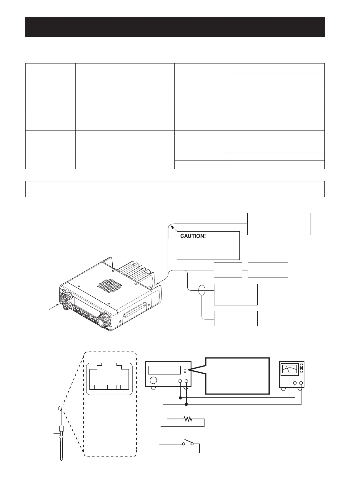
█REQUIRED EQUIPMENT
█CONNECTION
5-1 PREPARATION
*; For [TPE]. **; All models except [TPE].
*; For [USA].
Modulation
analyzer
to the antenna connector
Attenuator
40–60 dB
RF power meter
0.1–30 W*/50 Ω
0.1–70 W**/50 Ω
Frequency
counter
Standard signal generator
–20 to 90 dBµ
(–127 dBm to –17 dBm)
DO NOT transmit while
an SSG is connected to
the antenna connector.
JIG cable
8-pin modular jack
q
i
u
ytr e
w
q
w
e
r
t
y
u
i
8V
MICU/D
EXTMIC
PTT
MICE
MIC
GND
MICIN
y (MIC)
w (MICU/D)
u (GND)
r (PTT)
u (GND)
t (MICE)
AUDIO GENERATOR
(300–3000 Hz/1–500 mV)
+−
22 kΩ
+−
AC MILLIVOLTMETER
(10 mV to 10 V)
PTT
8-pin
modular
plug
To t h e MICROPHONE CONNECTOR
SETTING;
Frequency : 1 kHz
Level : 20 mVrms
(80 mVrms*)
Waveform : Sine wave
█JIG CABLE
CAUTION!: BACK UP the originally programmed memory data in the transceiver, before starting the adjustments.
When the adjustment is fi nished, the memory data may be cleared.
 Loading...