3-5
3
OPTIONS
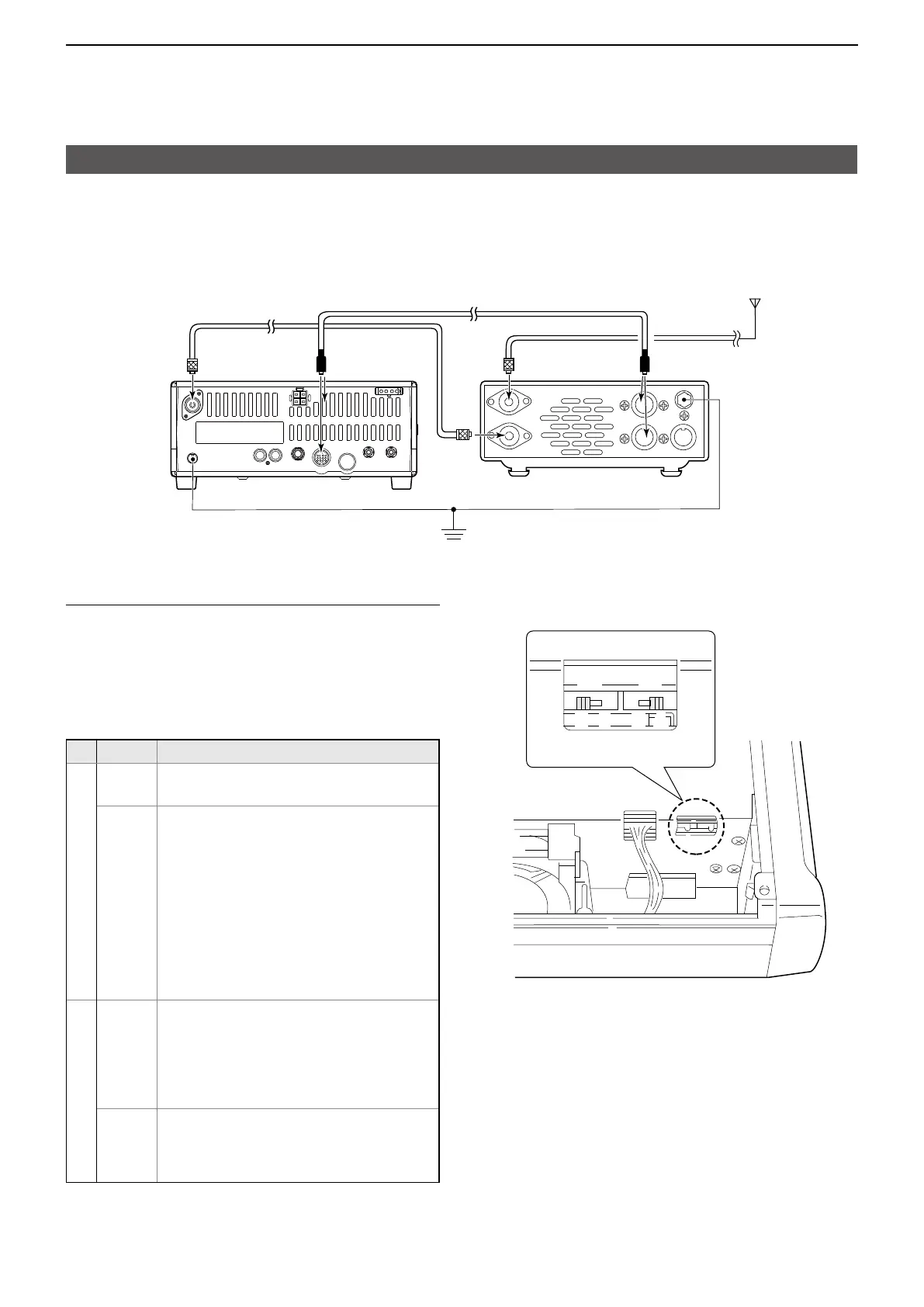
Setting the internal switches
The optional AT-180 has 3 operating settings�
Select the suitable setting for your antenna system�
1� Remove the top cover of the AT-180�
2� Set the tuner switches to the desired positions
according to the table below�
SW
Position Operation
S1
A
(default)
The tuner operating settings are set with
S2�
B THROUGH INHIBIT MODE
The tuner tunes the antenna even when the
antenna has poor SWR (up to VSWR 3:1
after tuning)�
In this case, manual tuning is necessary
each time you change the frequency,
although the tuner automatically starts tuning
when the VSWR is higher than 3:1�
This setting is called “through inhibit�”
However, the tuner is set to “through” if the
VSWR is higher than 3:1 after tuning�
S2
C TUNER SENSITIVE MODE
The tuner tunes each time you transmit
(except in the SSB mode)� Therefore, the
lowest SWR is obtained at any given time�
In the SSB mode, the setting is the same as
the “D” position�
D
(default)
NORMAL MODE
The tuner tunes when the SWR is higher
than 1�5:1� Therefore, the tuner activates
only when tuning is necessary�
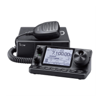
Connecting an external antenna tuner
D Using the AT-180
See also page 2-3 for the tuning operation�
AT-180 inside the top cover
S2 S1
D C B A
Coaxial cable supplied
with the AT-180
ACC cable supplied with the AT-180
either of two
[ACC] connectors
HF antenna
To [ACC]
To [ANT]
GND
IC-718 AT-180

 Loading...