97
12
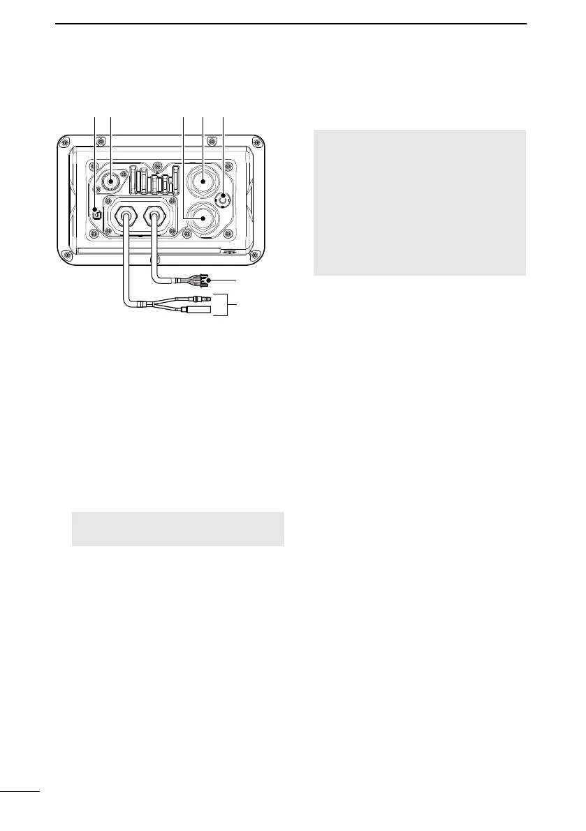
CONNECTIONS AND MAINTENANCE
wq r
e
t
y u
i
■ Connections
1GROUND TERMINAL
Connects to a vessel ground to prevent
electrical shocks and interference from
other equipment occurring.
Use a PH M3 × 6 screw (user supplied).
2ANTENNA CONNECTOR
Connects to a marine VHF antenna with
a PL-259 connector.
A key element in the performance of any
communication system is the antenna.
Ask your dealer about antennas and the
best place to mount them.
CAUTION: Transmitting without an
antenna may damage the transceiver.
3COMMAND MICROPHONE CONNECTOR
Connects the optional command
microphone.
4MICROPHONE CONNECTOR
Connects the supplied or optional
microphone.*
* Not usable when the microphone is
connected to the connector on the front
panel.
5GPS ANTENNA CONNECTOR
Connects to an optional GPS antenna.
NOTE:
• The GPS sentences input from this
connector takes precedence to over
the sentences input from the built-in
GPS receiver.
• Be sure the GPS antenna is
positioned where it has a clear view
to receive signals from satellites, and
pad supplied with the antenna.
6NMEA IN/OUT LEADS
Yellow: Listener A (Data-H), Data In (+)
Green: Listener B (Data-L), Data In (–)
Connect to the NMEA output lines of a
GPS receiver for position data.
• NMEA 0183 (ver. 2.0 or later) sentence
format RMC, GGA, GNS, or GLL
and VTG compatible GPS receiver is
required. Ask your dealer about suitable
GPS receivers.
• The GPS sentences input from this
connector are given priority to over the
sentences input from the built-in GPS
receiver.
• The AIS information through the AIS
device inputs as VDM sentence.
L The data communication speed (baud
(p. 85)
• For the versions with the AIS receiver,
precedence over the inputs from the
built-in AIS receiver.

 Loading...