TM 10-7360-226-13&P
CONTAINERIZED KITCHEN (CK) 0019 00
UNIT MAINTENANCE PROCEDURES
0019 00-3/4 Blank
attach a connector to it. Slip the new cable down through the cook center frame and junction
box. Attach the wire nuts and reassemble the junction box cover.
MBU: Refer to TM 10-7310-281-13&P for MBU repair procedures.
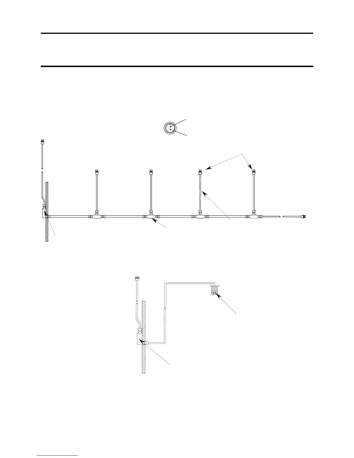
Figure 2. Cook Center 24 VDC MBU Cable Assembly.
END OF WORK PACKAGE
RED (POSITIVE)
BLACK (NEGATIVE)
CONNECTOR WIRING
JUNCTION BOX
MECHANICAL ROOM
JUNCTION BOX
24 VDC CABLE
MECHANICAL ROOM
JUNCTION BOX
28 VDC CONNECTOR IN CEILING RACEWAY
(CONNECTION TO DUAL OVEN ASSEMBLY AND
TRAY PACK HEATER)
CONNECTION TO COOK
CENTER MBUs
 Loading...