4 - 1
4-1 PREPARATION
‘‘
REQUIRED TEST EQUIPMENT
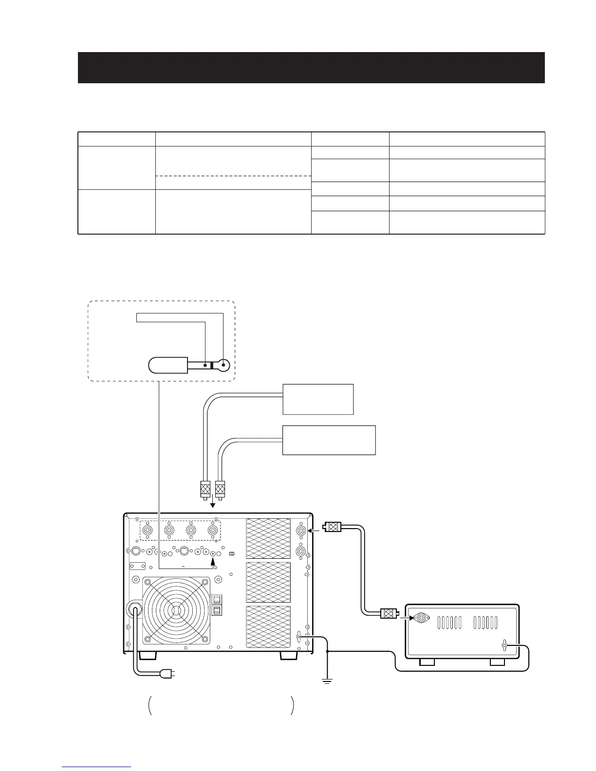
■ CONNECTION
EQUIPMENT
Exciter (Transceiver)
RF power meter
(terminated type)
GRADE AND RANGE
Frequency range : 1.8–60 MHz
Output power : 50–100 W
Mode : RTTY or FM
IC-736 (for tuner basis voltage adjustment)
Measuring range : 10–1500 W
Frequency range : 1.8–60 MHz
Impedance : 50 Ω
SWR : Less than 1.2 : 1
EQUIPMENT
Ammeter
RF dummy load
Digital DC voltmeter
DC voltmeter
Load-resistor
GRADE AND RANGE
Capability : 0.1–100 A
Impedance : 50, 100 and 150 Ω
Capability : 1500 W or more
Input impedance : 10 MΩ/V DC or better
Input impedance : 50 kΩ/V DC or better
Capability : 9.7–10.3 A
SECTION 4 ADJUSTMENT PROCEDURES
IC-PW1
EXCITER
Ground
Coaxial cable
Coaxial cable
to the ANT1 connector
RF power meter
1500 W/50
Ω
RF
dummy load
INPUT1
GND
GND
RF OUT
AC outlet
[USA] : 100–120/220–240 V
[EUR] and [EUR-1] : 230 V
Connect 2-conductor plug to REMOTE
connector when adjusting meter maximum
point.
1/8" (3.5 mm)
2-conductor plug
Shorten inner and outer plugs
 Loading...